
User's Manual


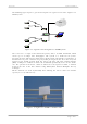
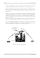
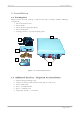

Table Of Contents
- GigAccess™ OFDM 5.8
- Installation and Operation Instructions
- TABLE OF CONTENTS
- TABLE OF TABLES
- TABLE OF FIGURES
- Introduction
- Installation
- GigAccess™ OFDM 5.8 Technical Specifications
- Appendix A – WaveIP Approved Antennas
- Appendix B – RF Link Budget Calculation
- Appendix C – RF Power and Distance versus Antenna Gain
- Appendix D – RF Hazard Distance Calculation
- Appendix E – RF Channel List
- Appendix F – Outdoor Cables Scheme
- Appendix G - Using the Unit Manager Tool

WaveIP Ltd. GigAccess™ OFDM 5.8
Pa
g
e 10 of 41
WARNING: It is the responsibility of the installer to insure that when using the
outdoor antenna kits in the United States (or where FCC rules apply),
only those antennas certified with the product are used. The use of any
antenna other than those certified with the product is expressly
forbidden in accordance to FCC rules part 15.247. The installer should
configure the output power level according to country regulations and
per antenna type.
3) Connect a ground cable between the Outdoor unit and an appropriate
grounding point.
4) Connect the Outdoor-to-Indoor CAT5 shielded cable to the Outdoor unit and
route it to the location selected for the Indoor Outlet. Assemble the enclosed
connector on the cable.
5) Mount the Indoor Outlet.
6) Connect the Outdoor-to-Indoor cable to the Indoor Outlet Radio port. (This
port supplies 48 VDC in addition to the Ethernet data).
7) Connect the CAT5 Ethernet cable from the user’s network/PC to the Indoor
Outlet data port.
8) Connect the power supply to the Indoor Outlet power port.
9) Align the antenna and verify connectivity of the Outdoor as follows:
• For SU - check connectivity to the base controller.
• For AU - check connectivity to the SU management IP address.
Connectivity check is done by ping instruction.
2
2
.
.
4
4
A
A
U
U
/
/
S
S
U
U
O
O
u
u
t
t
d
d
o
o
o
o
r
r
I
I
n
n
s
s
t
t
a
a
l
l
l
l
a
a
t
t
i
i
o
o
n
n
2
2
.
.
4
4
.
.
1
1
S
S
i
i
t
t
e
e
S
S
e
e
l
l
e
e
c
c
t
t
i
i
o
o
n
n
2
2
.
.
4
4
.
.
1
1
.
.
1
1
G
G
u
u
i
i
d
d
e
e
l
l
i
i
n
n
e
e
s
s
f
f
o
o
r
r
S
S
e
e
l
l
e
e
c
c
t
t
i
i
n
n
g
g
O
O
u
u
t
t
d
d
o
o
o
o
r
r
L
L
o
o
c
c
a
a
t
t
i
i
o
o
n
n
Select the appropriate locations for the outdoor unit using the following guidelines:
• The outdoor unit can be pole or wall mounted. Its location should allow easy
access to the unit for installation and testing.
• The AU should be installed where it provides coverage of all SUs in the area it
is intended to serve. The higher the AU or its detached antenna, the better
coverage it can provide.
• When using a detached antenna, the AU should be installed as near as possible
to its antenna.
2
2
.
.
4
4
.
.
1
1
.
.
2
2
A
A
c
c
c
c
e
e
s
s
s
s
U
U
n
n
i
i
t
t
(
(
A
A
U
U
)
)
Location of the Access Unit is on the Service Provider sole discretion considering local
topology and the desired cover. One (in case of Omni antenna) or several AUs (in
case of directional antenna) forms the BS (Base-Station) – the central of a cell. The
placement of AUs should be such that cells overlap slightly, to guarantee seamless
wireless connectivity everywhere. Neighboring AUs should preferably send and
receive on different channels or different polarization for maximum throughput
(minimum interference).