User Manual and Integrator’s Guide Boomer II OEM Modem Modules: BM2-800D BM2-900D Revision 3.
© Wavenet Technology Pty Ltd ACN 079 965 003 Publication No. BM210012WT37 Published November 2003 This publication is copyright and no part may be reproduced or copied without the prior consent of: Wavenet Technology Pty Ltd. 140 Burswood Rd Burswood, 6100 Western Australia Telephone: Facsimile: E-mail: Web Site: +61 8 9262 0200 +61 8 9355 5622 wavenet@wavenet.com.au www.wavenet.com.au This manual is intended to be used for the operation of Wavenet Technology equipment.
Boomer II User Manual & Integrator’s Guide __________________________________________________ Contents Contents Introduction ......................................................................................................6 Modem Features ..........................................................................................7 Wireless Applications ...................................................................................8 Developer Support ..................................................
Contents __________________________________________________ Boomer II User Manual & Integrator’s Guide Appendix A - NCL Interface ...........................................................................79 Generic NCL (Native Mode) .......................................................................79 Wavenet Specific NCL Extensions .............................................................84 Appendix B – SDK NCL-API and Port Server ................................................
Boomer II User Manual & Integrator’s Guide ________________________________________________ Introduction BM210012WT37 5 Copyright Wavenet Technology © November 2003
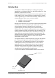
Introduction ________________________________________________ Boomer II User Manual & Integrator’s Guide Introduction The Boomer II OEM Modem Module is a radio packet modem, intended for use on Motorola DataTAC 4000 SFR and DataTAC 5000 MFR data communication networks. It is primarily designed to be integrated into customer equipment as an OEM module, for use with an Enterprise Application Server running wireless applications or as the RF communications enabler device for telemetry products.
Boomer II User Manual & Integrator’s Guide ________________________________________________ Introduction This manual contains the following major sections: Section 1: Introduction Section 2: The Integrator’s Task Section 3: Installing the Modem Section 4: Modem Test Jig Section 5: Wavenet Software Tools Section 6: Integration Testing In addition useful reference information has been included in the appendices.
Introduction ________________________________________________ Boomer II User Manual & Integrator’s Guide Wireless Applications Wireless applications in which the Boomer II OEM Modem may be used include the following: Meter Reading The modem can be used to read billing information from intelligent electrical meters and basic disc meters. Data is transmitted wirelessly through a radio network to billing computers.
Boomer II User Manual & Integrator’s Guide ________________________________________________ Introduction Developer Support A complete developers program is offered by Wavenet to assist integrators in the design, testing and implementation phases of their wireless applications. This includes a developer’s kit, modem software tools, sample source code and prototyping components. Wavenet’s experienced team of RF and software engineers are available to give technical support as required.
Introduction ________________________________________________ Boomer II User Manual & Integrator’s Guide Compliance Statement The Wavenet Boomer-II OEM Modem Module has been tested and found to comply with the limits for a class B digital device, pursuant to Part 15 of the FCC rules. These limits are designed to provide reasonable protection against harmful interference in a residential installation.
Boomer II User Manual & Integrator’s Guide ________________________________________________ Introduction Consult your supplier or an experienced radio/TV technician for assistance. Warning: Changes or modifications to this unit not expressly approved by the party responsible for compliance could void the user’s authority to operate this equipment.
Introduction ________________________________________________ Boomer II User Manual & Integrator’s Guide Copyright Wavenet Technology © November 2003 12 BM210012WT37
Boomer II User Manual & Integrator’s Guide ____________________________________________ Integrator’s Task The Integrator’s Task This section provides background information and points out the objectives and tasks of reaching the goal of a successful implementation. Areas of Focus Benefits Serial Port Pass-Through Capability Enables modem diagnostics and software upgrades without the need to disassemble the host/terminal Understanding RF Design Provides the required network coverage.
Integrator’s Task ____________________________________________ Boomer II User Manual & Integrator’s Guide Plan the Product and Create the Design To plan the product and create the design, perform the following steps: Develop a usage model. Develop a message model. Define a service strategy. Investigate and obtain regulatory approval.
Boomer II User Manual & Integrator’s Guide ____________________________________________ Integrator’s Task support for packet headers, the number of active users on a shared RF channel can directly affect network throughput. Define a Service Strategy The service strategy determines whether the integrated modem is the cause of a user’s problem and sets a policy for keeping the end user operational during repair.
Integrator’s Task ____________________________________________ Boomer II User Manual & Integrator’s Guide Diagnostic Capabilities To provide modem diagnostics, there are three LEDs on the modem itself. When the unit is first powered up it goes through its own self test and the status is reflected in the visual status of the LEDs. Customer Problem Isolation When application-visible problems are discovered in the field, you must isolate the source of the problem.
Boomer II User Manual & Integrator’s Guide ____________________________________________ Integrator’s Task Develop and Validate the Hardware To develop and validate the hardware, perform the following steps: Design the hardware platform Consider power supply options Select the source antenna Set up a development test environment Design the Hardware Platform Integrating a wireless modem into a hardware design requires many steps.
Integrator’s Task ____________________________________________ Boomer II User Manual & Integrator’s Guide evaluation board allows for maximum flexibility in accessing and controlling connections into and out of the modem. Wavenet also provides various software utilities that can help in performing development tests. See “Testing” on page 73.
Boomer II User Manual & Integrator’s Guide ____________________________________________ Integrator’s Task Wavenet provides a test facility for measuring host/terminal emissions and subsequent modem desense of integrated host/terminals. See “Desense and EMI” on page 74. In addition, see “Guide to Desense” on page 132.
Integrator’s Task ____________________________________________ Boomer II User Manual & Integrator’s Guide Wear a grounded anti static wrist strap while handling static sensitive components. Do not bend or stress the modem in any way. Reinsert connectors straight and evenly to avoid causing short and open circuits. ESD Handling Precautions The Boomer II OEM modem contains components sensitive to ESD (electrostatic discharge).
Boomer II User Manual & Integrator’s Guide ____________________________________________ Integrator’s Task Regulatory Requirements You are required to obtain regulatory approval of products that integrate the Boomer II OEM wireless modem into a host/terminal. The specific details for achieving regulatory approval vary from country to country.
Integrator’s Task ____________________________________________ Boomer II User Manual & Integrator’s Guide Country Requirements The country requirements given below are provided as a general guide to the certification processes in the regions and countries given. You are strongly encouraged to use the services of a consultant or a fullservice test house if you have limited expertise in meeting the regulatory requirements of a specific country.
Boomer II User Manual & Integrator’s Guide ____________________________________________ Integrator’s Task For “mobile or fixed devices”, defined as transmitting devices designed to be generally used such that a separation distance of at least 20 cm is maintained between the body of the user and the transmitting radiated structure, Maximum Permissible Exposure (MPE) limits may be used with field strength or power density limit of 0.537 mW/cm2 at 806 MHz or 0.597 mW/cm2 at 896 MHz.
Integrator’s Task ____________________________________________ Boomer II User Manual & Integrator’s Guide It is a requirement for integrated product certification that you provide the following statement in user documentation: “Regulatory Notice of Compliance This equipment has been tested and found to comply within the limits for a Class B digital device, pursuant to Part 15 of the FCC Rules.
Boomer II User Manual & Integrator’s Guide ____________________________________________ Integrator’s Task Canada Industry Canada (IC), formerly the Department of Communications, requires certification for all radio transceivers as either type-approved or technically accepted.
Integrator’s Task ____________________________________________ Boomer II User Manual & Integrator’s Guide Network profiles The networks in use in different countries each have a different list of channels and system parameters required for access to that network. These parameters must be configured in the modem.
Boomer II User Manual & Integrator’s Guide _________________________________________________Installation Installing the Modem This section will help you to successfully integrate the Boomer II OEM Modem into your custom application. When integrating a wireless modem, internal connections and placements are critical to a successful implementation.
Installation_________________________________________________ Boomer II User Manual & Integrator’s Guide Other considerations include mobile usage, which typically implies vehicular applications. Some of the design implications of mobile usage include: Resets The design must attempt to eliminate modem resets caused by supply voltage drops while the vehicle is starting. This is very disruptive to the network link.
Boomer II User Manual & Integrator’s Guide _________________________________________________Installation Proper mounting of the modem requires securely fastening it within the product housing. The mating surface should be flat and ensure a rigid mounting for the modem to minimise vibration to the unit. There should be an adequate supply of airflow to ensure the modem’s temperature limits are not exceeded.
Installation_________________________________________________ Boomer II User Manual & Integrator’s Guide The modem utilises connector part number 803-30-T-U from A-Point, however, connector equivalents such as F006-52893 from Molex as shown below, may also be used in the host/terminal. 20.4mm 14.5mm 14.5mm Molex FPC Connector F006-52893 Pin 1 of the connector is adjacent to the LED window and its location is shown below.
Boomer II User Manual & Integrator’s Guide _________________________________________________Installation Data Interface Pin Descriptions Pin Signal Description Signal Reset State 1 DCD Data Carrier Detect Output High Impedance 2 RXD Receive Data Output High Impedance 3 TXD Transmit Data Input 100k pull up to 3.3V 4 DTR Data Terminal ready Input 100k pull up to 3.
Installation_________________________________________________ Boomer II User Manual & Integrator’s Guide Modem On/Off Control The modem on/off input line (HOSTPWR_ON) is an active high input signal and is fitted with a 33Ω series resistor and clamp diode to the internal supply line for input protection. Internally it is passively pulled low (after the series resistor) via a 56kΩ pull-down resistor to ground and is asserted with an actively driven high signal.
Boomer II User Manual & Integrator’s Guide _________________________________________________Installation Modem Reset Input The reset input line (HCRESET) is an active low input signal (TTL compatible) and is fitted with a 6.8kΩ series resistor and clamp diode to the internal supply line for input protection. Internally it is passively pulled high (after the series resistor) to the supply rail (3.3V) and is asserted with an actively driven low signal to ground.
Installation_________________________________________________ Boomer II User Manual & Integrator’s Guide Serial Communications Equivalent Circuit Serial Communications Electrical Characteristics Parameter Range Low High 0-3.3 V OR 0-5V 0.8 V (max) 2.5 V (min) 0 – 3.3 V 0.5 V (max) 2.3 V (min) Input Current 100 µA (max) 100 µA (max) Output Current 3.2 mA (max) 1.
Boomer II User Manual & Integrator’s Guide _________________________________________________Installation J1 Pin # Signal Description Signal Active State data throttling 9 RI Ring indicator Output Pulses Low when messages are waiting Status Input / Output lines Note: Not currently supported but may be added in future releases. The status lines (SS0 to SS3) may be software configured for bidirectional operation.
Installation_________________________________________________ Boomer II User Manual & Integrator’s Guide Status Input/Output Interface Definitions J1 Pin # Signal 16 SS0 Status Signal 0 Input/ Output User configurable (future option) 17 SS1 Status Signal 1 Input/ Output User configurable (future option) 18 SS2 Status Signal 2 Input/ Output User configurable (future option) 19 SS3 Status Signal 3 Input/ Output User configurable (future option) Description Signal Active State LED Ind
Boomer II User Manual & Integrator’s Guide _________________________________________________Installation LED Output Lines In addition to the on-board LED’s there are three signal lines (Low Battery, Message Waiting, In-range), which are controllable by the modem for connection to an external LED. Each line has a 33Ω series resistor and clamp diode to the internal supply line for protection. It is recommended a series resistor be used with the external LED to limit current accordingly.
Installation_________________________________________________ Boomer II User Manual & Integrator’s Guide very fast transition between voltages, it may take up to 20 seconds for the modem to confirm a change in battery status. Message Waiting The Message waiting signal is held active low whenever there is at least one complete message waiting in the outbound buffers (including the reread buffer). In-Range The In Range signal is held active low whenever the modem is in range.
Boomer II User Manual & Integrator’s Guide _________________________________________________Installation market relatively thin double braid coaxial cables. These cables show much better isolation than single braid cables, typically by 30 to 40dB. These double braid cables reduce radiation and RF pick-up when routed inside a portable device.
Installation_________________________________________________ Boomer II User Manual & Integrator’s Guide Compliance Statement on page Error! Bookmark not defined. Impedance: 50Ω Centre Frequency: 833MHz ± 5MHz (for 800MHz modem) 921MHz ± 3MHz (for 900MHz modem) Frequencies of operation: 806 to 825MHz (for 800MHz transmit) 851 to 870MHz (for 800MHz receive) 896 to 902MHz (for 900MHz transmit) 935 to 941MHz (for 900MHz receive) Acceptable return loss: VSWR < 1.5 or RL < -14dB (recommended) VSWR < 2.
Boomer II User Manual & Integrator’s Guide _________________________________________________Installation Connecting the Antenna The Boomer II OEM Modem Module provides an MMCX RF connector located at the top of the unit, to attach to the antenna cable. The antenna does not plug directly into the modem but uses an antenna cable to interface between the device and the modem. The antenna cable should be a low loss, 50Ω impedance and have a MMCX plug that can mate with the modem’s MMCX socket.
Installation_________________________________________________ Boomer II User Manual & Integrator’s Guide Source Based Time Averaging Function For portable or handheld applications the integrated host/terminal must comply with OET Bulletin 65 and Supplement C (June 2002) with respect to Specific Absorption Rate (SAR) requirements. The Boomer-II modem module operates on a packet data network which sets the timing of most aspects of the RF signalling protocol.
Boomer II User Manual & Integrator’s Guide _________________________________________________Installation The Boomer-II modem module has an overall transmit Duty Cycle limitation of 30% (maximum) to physically protect the modem hardware. The default Duty Cycle preset in the factory at the time of manufacture is 10%. Other duty factors and SAR evaluation must be addressed at the time of OEM integration into any final host/terminal product and is the responsibility of the OEM Integrator.
Installation_________________________________________________ Boomer II User Manual & Integrator’s Guide Supplying Power The Boomer II OEM Modem must be provided with a clean power source capable of delivering bursts of high current. The modem draws its power in bursts. The power required changes rapidly depending on whether the modem is transmitting, receiving or on standby. Ratings The power supply requirements are: Voltage: 3.8V (3.4 to 4.2V range) Transmit Current: 1.6A maximum (2.
Boomer II User Manual & Integrator’s Guide _________________________________________________Installation The power supply should be set above nominal 3.8V to accommodate worst case power supply drop. i.e. 4.0V. The power supply should have good regulation with < 200mV drop at 2.2A. Adequate supply decoupling (10,000uF min.) is added at terminal connector to reduce ripple and smooth supply voltage steps. The power supply be capable of supplying non-ideal current consumption conditions of up to 2.
Installation_________________________________________________ Boomer II User Manual & Integrator’s Guide Off The modem is turned off or the host/terminal (battery) has failed. Sleep The processor is sleeping and wakes up to an interrupt, but the RF section is off. Receive The processor is actively processing information; the RF sections are on and demodulating data. Transmit The processor is actively processing information; the RF sections are on and transmitting data.
Boomer II User Manual & Integrator’s Guide _________________________________________________Installation Some applications require the use of group LLIs, such as a stock quotation broadcast service. Each active group LLI (in addition to the modem's factory loaded individual LLI) increases the percentage of time the modem stays in the receive state, thereby increasing its overall current consumption.
Installation_________________________________________________ Boomer II User Manual & Integrator’s Guide Power-Up Timing Diagram Optional Delay HOST 3.
Boomer II User Manual & Integrator’s Guide _________________________________________________Installation Power Down Sequence The host/terminal may request the modem to turn OFF by de-asserting the HOSTPWR _ON or by sending a specific NCL command across the serial interface. For the modem to turn OFF after an NCL request the HOSTPWR_ON signal must be de-asserted. Warning: The power supply rail must be maintained during a power down sequence or else memory may be corrupted.
Installation_________________________________________________ Boomer II User Manual & Integrator’s Guide Power Down Diagram Callouts 1 HOSTPWR_ON is de-asserted from the host/terminal to the modem. Important: The power rail must be present for up to ten seconds (typically two seconds) after HOSTPWR_ON is de-asserted for the deregistration process to complete orderly. 2 The modem starts the soft shutdown process. The battery status indicator pulses quickly until the shutdown steps are complete.
Boomer II User Manual & Integrator’s Guide _________________________________________________Installation Batteries The Boomer II OEM Modem may be powered by batteries if used with a handheld device. For battery operated devices, battery selection is a critical decision, requiring consideration of many factors. These include cell size, internal impedance, charging requirements, and susceptibility to common battery phenomena, such as memory effect or overcharging.
Installation_________________________________________________ Boomer II User Manual & Integrator’s Guide NiMH Mature technology with potential for improvements in battery chemistry and energy density over the next five years Higher energy density than NiCad, but lower than Li-ion Available in standard sizes AA, 2/3A, 4/5A, A and 4/3A and some prismatic (rectangular) configurations Exhibits the memory effect in a manner similar to NiCad technology, but at a less pronounced level Internal impedance of 35-49µ
Boomer II User Manual & Integrator’s Guide _________________________________________________Installation Li-ion batteries are very sensitive to over-discharge and represent a hazard if not properly designed with protection circuitry. Typical charge method is constant-voltage, constant-current. Applying Battery Technologies When reviewing different battery technologies, consider the following characteristics of OEM devices incorporating wireless data modems.
Installation_________________________________________________ Boomer II User Manual & Integrator’s Guide Battery Recharging Plug-in Supplies A mains plug-in supply must be designed to ensure that voltage spikes, lightening and other power fluctuations cannot damage the Boomer II. Transient voltage protection zener diodes or other spike arrestor circuits may be added to keep the inputs within the power requirements mentioned previously.
Boomer II User Manual & Integrator’s Guide ____________________________________________ Modem Test Jig Using the Modem Test Jig The Boomer II Test Jig provides RS-232 serial interface ports between a PC and the modem. It is designed to enable you to quickly interface the Boomer II to a standard PC (through a COM port) or a terminal device with an RS-232 serial port.
Modem Test Jig ____________________________________________ Boomer II User Manual & Integrator’s Guide Exploring the Boomer II Test Jig The test jig comprises the following components: DC Jack Input Supply On/Off Switch 3 RDW Header connector VCC test pin 3.
Boomer II User Manual & Integrator’s Guide ____________________________________________ Modem Test Jig Port 2 / SPY PC Connector DB9 connector used for two purposes depending upon the settings of the jumper switches located just behind the connector on the PCB. If the jumpers are used to connect the centre column to the right hand outer column (TX, RTS etc), then the port acts as a spy connection for the data between the PC and the modem via the PC connector. An analyser program such as “spy.
Modem Test Jig ____________________________________________ Boomer II User Manual & Integrator’s Guide Audio Out Connector for monitoring an audio output. Used to monitor base band signal, BIT Error Rate (requires a PER test jig), receiver and demodulation. Warning: Must use a high impedance monitor, 100kΩ. Audio In Connector for monitoring an audio input. Used to monitor modulation and transmission. Warning: Must use a high impedance monitor, 100kΩ.
Boomer II User Manual & Integrator’s Guide ____________________________________________ Modem Test Jig Initial Calibration Without connecting a Boomer II OEM Modem to the Test Jig, initially check the calibration of the on-board voltage regulator. (This regulator supplies the RS232 converter and other on-board circuitry only. It does not supply power to the modem). 1. Connect the centre pin of the DC jack to the +3.8V power supply with 2A capability and the external pin to the ground. 2.
Modem Test Jig ____________________________________________ Boomer II User Manual & Integrator’s Guide c. Press down the lock lever. Note: If the cable has been partially inserted, or out of alignment, the lock lever will not engage. Should this occur, remove the cable (see below) and repeat steps a-c. Use the following procedure to remove the cable from the FPC connector. a. Lift up the lock lever of the FPC connector by flipping it up with the nail of your thumb or index finger. Lock Lever b.
Boomer II User Manual & Integrator’s Guide __________________________ Wavenet Software Development Tools Software Development Tools Wavenet SDK DataTAC networks allow wireless communication and are installed in many different countries around the world. The Wavenet Software Development Kit (SDK) has been developed to facilitate development of applications for these networks by providing a simple program interface for communicating with the network devices.
Wavenet Software Development Tools___________________________ Boomer II User Manual & Integrator’s Guide Run as PortServer comx: Where "x" is the PC communications port the modem is attached to via a Boomer II Test Jig. If no command line parameter is specified, 'PortServer' assumes that 'com1' is to be used. Note: The port server must be running for the Client applications to work with the Multisession VDD. The port server must not be running for the Client applications to work with the Singlesession VDD.
Boomer II User Manual & Integrator’s Guide __________________________ Wavenet Software Development Tools System Requirements The minimum system requirements of a host/terminal emulation PC in order to utilise the Software Developers Kit are: Intel compatible Pentium computer or higher Windows 2000 or later Microsoft Message Queue (MSMQ) 16MB RAM (memory) minimum, 32MB recommended 1MB available hard disk space 9-pin serial Port using a 16550 UART 3.
Wavenet Software Development Tools___________________________ Boomer II User Manual & Integrator’s Guide Server Initialisation The port server must be running for the Client applications to work. ‘PortServer.exe’ takes the desired serial port name as a command line parameter. If no command line parameter is specified, ‘PortServer’ assumes that ‘com1’ is desired. Start the server application by running ‘PortServer.exe’. If com2 is connected to the modem, run the server as following: PortServer com2.
Boomer II User Manual & Integrator’s Guide __________________________ Wavenet Software Development Tools Wavenet Commander The radio service utility software “Wavenet Commander” enables a user to exercise and configure Wavenet Modems. This software runs under Windows 95, 98, NT, or 2000. Wavenet Commander interfaces with the Boomer II OEM Modem via a PC’s communications port and the Test Jig’s PC port using an RS-232 cable.
Wavenet Software Development Tools___________________________ Boomer II User Manual & Integrator’s Guide Operations Wavenet Commander display is broken up to four quadrants as follows: Upper-Left Upper-Right “Modem Info” Tree View “Modem Info” Property View The modem Type and display options are represented as Tree view. Use the mouse to select the following modem information views. Displays the associated property pages as selected by the quick link in the tree view.
Boomer II User Manual & Integrator’s Guide __________________________ Wavenet Software Development Tools Ensure the test jig with the modem is powered up and connected (Serial cable from PC port of the Test Jig to your PC’s Communication port) and the above the communication settings are correct for your set-up. Modem Info Tree View ModemInfo uses the NCL API to interface to the DataTAC® network.
Wavenet Software Development Tools___________________________ Boomer II User Manual & Integrator’s Guide TTY Control View The TTY control View allows the user to perform the following: • Display detailed commands and responses. The commands to the modem and the responses from the modem are displayed in Hex format. A maximum of 200 bytes is displayed per command or response. • Allows the user to enable / disable the wc.log file.
Boomer II User Manual & Integrator’s Guide __________________________ Wavenet Software Development Tools Wavenet Application Loader The Application Loader software is used to upgrade the resident software installed on your Wavenet OEM modem. For optimum performance ensure that you are using the latest application version. This appendix explains the procedure for updating the Application Loader software and has a troubleshooting section to assist with any problems.
Wavenet Software Development Tools___________________________ Boomer II User Manual & Integrator’s Guide Note: The message shown above will appear if you are attempting to upgrade using ApploaderM408.exe with a BM2 modem. Select the appropriate com port on your PC that the modem is connected to. Click the Download Application button to download the latest version. Displays the current version of Application software on your modem. 7. The following screen is typically displayed.
Boomer II User Manual & Integrator’s Guide __________________________ Wavenet Software Development Tools 13. A message is then displayed in the status bar, informing you that that the application software on the modem is up to date. 14. Click the modem. to exit the program. This will automatically reset Troubleshooting You shouldn’t encounter any problems updating the Application Loader software, however the following messages may appear.
Wavenet Software Development Tools___________________________ Boomer II User Manual & Integrator’s Guide This message (or similar) will appear if you have attempted to upgrade your modem with the incorrect Application Loader file. The letter preceding the three numerical characters at the end of the Application loader file name denotes which modem the file is appropriate for, i.e. BM2 for the Boomer II OEM modem.
Boomer II User Manual & Integrator’s Guide ___________________________________________________ Testing Integration Testing This section contains a product development checklist of parameters to check, requirements to meet, and standards of performance to evaluate. You can use these process checks and functional test procedures to fully qualify that the Boomer II OEM Modem has been integrated properly into the host/terminal.
Testing ___________________________________________________ Boomer II User Manual & Integrator’s Guide the modem and host/terminal. Ensure that the following hardware integration issues are evaluated: RF Immunity RF transmissions of the modem do not interfere with operation of the host/terminal. Electrical Signalling Power sources and interface are functionally compatible between the host/terminal and the modem.
Boomer II User Manual & Integrator’s Guide ___________________________________________________ Testing modem . The ability to turn on and off the various circuits in the host/terminal allows for the identification and analysis of the host/terminal components that are responsible for desense. This approach to desense troubleshooting can greatly speed up the OEM integration effort. For more detailed information about desense, refer to “Guide to Desense” on page 132.
Testing ___________________________________________________ Boomer II User Manual & Integrator’s Guide Application Software Tests need to verify the communications links between the host/terminal and the modem and between the modem and the network, as follows: Software Driver Configuration Ensure that the host/terminal can enable the modem serial port to permit the host/terminal and modem to communicate. This test verifies that the driver software functions well and is configured properly.
Boomer II User Manual & Integrator’s Guide ___________________________________________________ Testing Effective tests provide a systematic, positive acknowledgment from each of the network components.
Testing ___________________________________________________ Boomer II User Manual & Integrator’s Guide Copyright Wavenet Technology © November 2003 78 BM210012WT37
Boomer II User Manual & Integrator’s Guide ________________________________ Appendix A - NCL INTERFACE Appendix A - NCL Interface The Boomer II is compliant to Native Control Language (NCL) 1.2. Wavenet Vendor-specific extensions are also listed here. The specification for the NCL protocol may be obtained in Adobe Acrobat format from the Motorola website at http://www.mot.com/MIMS/WDG/pdf_docs/8-.pdf Please note that the Boomer II modem can also be configured to approximate a Hayes protocol.
Appendix A - NCL INTERFACE ________________________________ Boomer II User Manual & Integrator’s Guide Commands SET_CNF Value Parameters Value Sub-values and Descriptions R_RX_STATUS ASCII b Get receiver enable status. R_TX_STATUS ASCII c Get transmitter enable status. R_ANTENNA ASCII d Get antenna selection status. R_RADIO_IN_RANGE ASCII e Get radio in range status. R_OB_MSG_COUNT ASCII f Count of outbound messages queued. R_IB_MSG_COUNT ASCII g Count of inbound messages queued.
Boomer II User Manual & Integrator’s Guide ________________________________ Appendix A - NCL INTERFACE Commands Value Parameters Value Sub-values and Descriptions S_BAUD ASCII K Set the baud rate for NCL communications: S_ANTENNA RESET_RPM VENDOR BAUD_1200 1200 baud ASCII 0 BAUD_2400 2400 baud ASCII 1 BAUD_4800 4800 baud ASCII 2 BAUD_9600 9600 baud ASCII 3 BAUD_19K2 19200 baud ASCII 4 BAUD_38K4 38400 baud ASCII 5 Undefined Select the antenna ASCII L..Z Reserved.
Appendix A - NCL INTERFACE ________________________________ Boomer II User Manual & Integrator’s Guide channel. RX_REG_DENIED HW_EVENT ASCII E HW_EVENT_BIT $01 ASCII 2 Low battery. ASCII 3 Memory full. HW_BATT_OK ASCII 4 Battery level OK. HW_MEM_OK ASCII 5 Memory OK. HW_OFF ASCII 6 Device shutdown imminent. HW_BATT_WARN ASCII 7 Battery at warning level. ASCII F ASCII G Self-test failed. HW_MEM_FULL Unreceivable message event. CONTROL_BIT ASCII 1 $20 ACK required, PDU received.
Boomer II User Manual & Integrator’s Guide ________________________________ Appendix A - NCL INTERFACE ASCII P..Y, 1..9 SYNTAX VENDOR ASCII 3 ASCII Z BM210012WT37 Reserved. Command SDU syntax error. Note the following error codes: INVALID ASCII b Invalid options. TOO_LONG ASCII c Data is too long. ASCII Z Vendor-specific response.
Appendix A - NCL INTERFACE ________________________________ Boomer II User Manual & Integrator’s Guide Wavenet Specific NCL Extensions The following table describes Wavenet specific extensions to the NCL 1.2 specification. All SDUs include three VENDOR control byte and the vendor Id. (the ‘\’ character is used as an escape character for hexadecimal bytes below): Command Type 1. Get status commands 2. Generic “Set RPM configuration” command type 1.
Boomer II User Manual & Integrator’s Guide ________________________________ Appendix A - NCL INTERFACE OPERAND DESCRIPTIONS AND RESPONSES: The various Vendor Status Requests that can be made, and the format of their response information in the SUCCESS response SDU, are described as follows. Please note that all multiple byte fields are stored MSB first. WN_GET_RADIO: Get radio status information (NCL string “ZF?r”).
Appendix A - NCL INTERFACE ________________________________ Boomer II User Manual & Integrator’s Guide WN_GET_BATT_VOLT: (NCL string “ZF?v”). Get modem battery status information SUCCESS is followed by a block of status information in the format shown below: WN_GET_BATT_VOLT Response Format: 7 6 5 4 3 2 1 0 Battery Voltage (2 bytes) Battery Percentage Where: Battery Voltage: Two byte unsigned integer representing the Voltage of the battery in mV.
Boomer II User Manual & Integrator’s Guide ________________________________ Appendix A - NCL INTERFACE WN_GET_SETTINGS: string “ZF?u”). Get configuration information (NCL SUCCESS is followed by a block of status information in the format shown below: WN_GET_SETTINGS Response Format: 7 6 5 4 3 2 1 0 LLI [4 bytes] Serial Number [16 bytes] .......
Appendix A - NCL INTERFACE ________________________________ Boomer II User Manual & Integrator’s Guide indicates disabled, a one indicates enabled. NCL Event Flags: Byte which indicates the start-up state of the NCL event reporting. A set bit indicates the relevant event is enabled. A cleared bit indicates the event is disabled.
Boomer II User Manual & Integrator’s Guide ________________________________ Appendix A - NCL INTERFACE FORMAT: WN_SET_PARAM Command Syntax (NCL string “ZF^…”): CMND Length SDU Tag VENDOR ‘Z’ ‘F’ VEND_WAVENET ‘^’ Parameter number Parameter length WN_SET_PARAM WN_SET_PARAM Response Syntax: RESP Length SDU Tag VENDOR VEND_WAVENET SUCCESS OPERAND DESCRIPTIONS AND RESPONSES: The various Vendor Parameter settings that can be made are described as follows.
Appendix A - NCL INTERFACE ________________________________ Boomer II User Manual & Integrator’s Guide Parameter length : Parameter contents : 0x0001 (“Byte3Byte4”) One unsigned byte (“Byte5”) indicating the Power Save mode as follow: ASCII ‘0’ : EXPRESS (Disabled Power Save or “full awake” mode). ASCII ‘1’ : MAXIMUM (4 windows). ASCII ‘2’ : AVERAGE (8 windows). ASCII ‘3’ : MINIMUM (16 windows).
Boomer II User Manual & Integrator’s Guide ________________________________ Appendix A - NCL INTERFACE Generic set RPM Configuration command type 2 This command allows the DTE to set the configuration settings of certain aspects of the modem.
Appendix A - NCL INTERFACE ________________________________ Boomer II User Manual & Integrator’s Guide Generic get RPM Configuration command (WN_GET_PARAM): This command allows the DTE to get the configuration settings of certain aspects of the modem. This section should be seen together with the previous section (“Generic GET RPM Configuration command”).
Boomer II User Manual & Integrator’s Guide ________________________________ Appendix A - NCL INTERFACE WN_GET_PROFILE_LIST Response Format: Number of profiles (n) [1 byte] Active profile number [1 byte] Profile Name 1 (up to 24 byte null terminated string) Profile Name 2 (up to 24 byte null terminated string) . . . Profile Name n (null terminated string) [24 bytes] Where: Number of profiles: Unsigned byte giving the current number of profiles in configuration sector. The number of profiles may change.
Appendix A - NCL INTERFACE ________________________________ Boomer II User Manual & Integrator’s Guide Copyright Wavenet Technology © November 2003 94 BM210012WT37
Boomer II User Manual & Integrator’s Guide ______________________Appendix B – SDK NCL-API and Port Server Appendix B – SDK NCL-API and Port Server The Native Control Language Application Programmer's Interface (NCL API) is the client component of the SDK. The NCL API provides routines for sending and receiving data messages through the DataTAC wireless network, using a radio packet modem (RPM).
Appendix B – SDK NCL-API and Port Server______________________ Boomer II User Manual & Integrator’s Guide Layer 6 (Presentation) Layer 5 (Session) Level 4 (Transport ) MSMQ MSMQ IN 1 TX Queue MSMQ IN N Message Router & NCL Interpreter Layer 3 (Network) Serial Port Drivers Layer 2 (Data) )))Li k) Layer 1 (Physical) Serial Port to modem Wavenet NCL API Model Logical Architecture The following table lists the required functionality for the API per layer.
Boomer II User Manual & Integrator’s Guide ______________________Appendix B – SDK NCL-API and Port Server LAYER NAME 1. PHYSICAL / BIT TRANSFER LAYER CONTENT FUNCTION Extender Port to RPM. 9600, 8, 1, N on serial port and a wakeup line. Wavenet’s current NCL API protocol stack is implemented with the hierarchical structure. All DLLs including MSMQ files are included in the install cabinet files for the VDD. Message Router The PC or PPC loads MSMQ as a device driver.
Appendix B – SDK NCL-API and Port Server______________________ Boomer II User Manual & Integrator’s Guide Multisession API: If successful this operation will result in the creation of two MSMQ queues for use by the client. One MSMQ will be used to send messages from the VDD to the client and the other for messages from the client to the VDD. Note that the client does not deal with MSMQ queues directly because all operations are wrapped in API calls. The Multisession API can only use the VDDOpen call.
Boomer II User Manual & Integrator’s Guide ______________________Appendix B – SDK NCL-API and Port Server Close Session Applications can call this function to close its session with the VDD. An application should call this function before it terminates if a session was earlier established with the VDD. The reason for this in the multisession API is to ensure that all created MSMQ queues for the client are deleted. This will prevent irrelevant/outdated messages from being posted to inactive MSMQ queues.
Appendix B – SDK NCL-API and Port Server______________________ Boomer II User Manual & Integrator’s Guide Description: Send application data to the radio host identified by the host ID. Input: UsSduTag Pointer to a word where the SDU tag can be stored SzHostId Pointer to a buffer specifying the Host identity. The Host ID is typically 3 bytes in length for DataTac systems. The NCL API will truncate Host ID’s longer than NCL_MAX_UH_LEN (63) bytes in length.
Boomer II User Manual & Integrator’s Guide ______________________Appendix B – SDK NCL-API and Port Server contain an SDU tag equal to 65535. The received event/ response messages will be represented as an array of bytes which must be typed cast to a structure identified by returned structure ID. The RCV_MSG_NOTIFICATION event will be handled by the VDD, which will read the messages from the RPM and pass the messages to all clients with open sessions.
Appendix B – SDK NCL-API and Port Server______________________ Boomer II User Manual & Integrator’s Guide /*** Define types for retrieving data from the RPM ***/ typedef unsigned char typedef unsigned short BYTE; WORD; /*Parameter Structure IDs - Do not alter sequence*/ enum { NCLNone_ID = 0, NCLEvent_ID, NCLProdId_ID, NCLVersion_ID, NCLRpmId_ID, NCLConfigBlock_ID, NCLStatusBlock_ID, NCLChanBlock_ID, NCLGroupLlis_ID, NCLChannelTable_ID, NCLWaveSettings_ID, NCLWaveRadio_ID, NCLWaveGen_ID, NCLByte_ID, NCLB
Boomer II User Manual & Integrator’s Guide ______________________Appendix B – SDK NCL-API and Port Server NCLProdId NCLVersion NCLRpmId WORD WORD }NCLConfigBlock; /* Status block structure */ typedef struct NCLStatusBlock { BYTE BYTE BYTE BYTE BYTE BYTE BYTE WORD WORD WORD }NCLStatusBlock; /* Channel block structure */ typedef struct NCLChanBlock { BYTE WORD BYTE BYTE BYTE }NCLChanBlock; prod_id; sw_version; rpm_id; reserved; max_data_size; rx_status; tx_status; antenna; radio_in_range; flow_control; rcv
Appendix B – SDK NCL-API and Port Server______________________ Boomer II User Manual & Integrator’s Guide typedef struct NCLWaveRadio { BYTE BYTE BYTE BYTE BYTE BYTE BYTE BYTE BYTE BYTE BYTE BYTE } NCLWaveRadio; rssi[2]; reserved1; reserved2; reserved3; reserved4; reserved5; reserved6; reserved7; reserved8; frequency[4]; channel[2]; base_id; /* Vendor Spesific: Wavenet Generic*/ typedef struct NCLWaveGen { BYTE byte[100]; } NCLWaveGen; /* NCL status information structure */ typedef union NCLStatus { NCLP
Boomer II User Manual & Integrator’s Guide ______________________Appendix B – SDK NCL-API and Port Server /* NCL_RCV_ERR_EVENT /* NCL_CONTROL_EVENT 'F' 'G' Unreceivable Message Event Control Event */ */ BYTE EventCode; /* NCL_MSG_NOTIFICATION_LEN N- Number of buffered msgs to be read */ /* NCL_TX_EVENT_KEYED ‘1’ Transmitter keyed */ /* NCL_TX_EVENT_DEKEYED ‘2’ Transmitter dekeyed */ /* NCL_RX_EVENT_INRANGE ‘1’ RF in range */ /* NCL_RX_EVENT_OUTRANGE ‘2’ RF out of range */ /* NCL_RX_EVENT_PSENAB ‘3’ Pow
Appendix B – SDK NCL-API and Port Server______________________ Boomer II User Manual & Integrator’s Guide Status Request (non vendor specific) Response Structure Description DTE for received SDUs. NCL_R_RX_STATUS NCLStatus.rx_status Get receiver enable status NCL_R_TX_STATUS NCLStatus.tx_status Get transmitter enable status NCL_R_ANTENNA NCLStatus.antenna Get antenna selection status NCL_R_RADIO_IN_RANGE NCLStatus.radio_in_range Get radio in range status NCL_R_OB_MSG_COUNT NCLStatus.
Boomer II User Manual & Integrator’s Guide ______________________Appendix B – SDK NCL-API and Port Server requests ucType The type of status information to retrieve from the RPM (Used by Vendor specific requests). Set to zero for non-vendor requests or WN_GET_STATUS = ‘?’ for Wavenet Technology specific requests ucRequest The requested status information, as listed in one of the appropriate tables above, to retrieve from the RPM.
Appendix B – SDK NCL-API and Port Server______________________ Boomer II User Manual & Integrator’s Guide Description: Command the RPM to perform a specified level reset Input: usSduTag Pointer to a word where the SDU tag can be stored ucResetLevel The level of the Reset as listed in the above table Output: Return value = 0 Operation was successful Return value ≠ 0 Operation failed.
Boomer II User Manual & Integrator’s Guide ______________________Appendix B – SDK NCL-API and Port Server Input: iSessionID VDD session ID usSduTag Pointer to a word where the SDU tag can be stored ucType The type of event to enable/disable: NCL_RCV_MSG_DATA (Received message data) NCL_TX_EVENT (Physical-level transmitter event) NCL_RX_EVENT (Physical-level receiver event) NCL_HW_EVENT (Hardware event) NCL_RCV_ERR (Un-receivable message event) NCL_CONTROL (Control event) NCL_VEND_EVENT (Vendor specifi
Appendix B – SDK NCL-API and Port Server______________________ Boomer II User Manual & Integrator’s Guide Error Code Value Description NCL_ERR_INVALID 'b' NCL Syntax error: Invalid options NCL_ERR_TOO_LONG 'c' NCL Syntax error: Data too long NCL_ERR_ES_NAME 'd' NCL Syntax error: Invalid name NCL_ERR_NO_RESPONSE 'A' Execution error: No response from network NCL_ERR_NO_ACK 'B' Execution error: Negative ACK received NCL_ERR_HOST_DOWN 'C' Execution error: Host down NCL_ERR_NOT_REGISTERED
Boomer II User Manual & Integrator’s Guide ______________________Appendix B – SDK NCL-API and Port Server Register Wakeup Application By default the VDD is executed on wakeup. In addition an application can register to be executed on wakeup via the VDD. On wakeup the VDD will post any Received data to the current active queues. If there are no active queues the VDD will execute the Registered applications. Once an application has initiated a successful VDD session (i.e.
Appendix B – SDK NCL-API and Port Server______________________ Boomer II User Manual & Integrator’s Guide Description: Deregister a wakeup application. Input: usAppName Pointer to a buffer specifying the full path name (Null terminated) of the application to execute on a wakeup. Output: Return value = 0 Operation was successful Return value ≠ 0 Operation failed. Value specifies the error type Switch RPM On/Off The application can call this function to switch the RPM on or off.
Boomer II User Manual & Integrator’s Guide ______________________Appendix B – SDK NCL-API and Port Server Send an NCL command to the RPM of which the payload contents consist of data from the specified buffer. Input: usSduTag Pointer to a word where the SDU tag can be stored ucLength Pointer to a byte specifying the total size of ucParam.
Appendix C – SDK Sample Programs ___________________________ Boomer II User Manual & Integrator’s Guide Appendix C – SDK Sample programs Sample programs are provided with the SDK. The purpose of the sample programs is to show how a complete working client server application can be built using the SDK NCL API with the client program.
Boomer II User Manual & Integrator’s Guide ___________________________ Appendix C – SDK Sample Programs The Status tab displays the modem’s current channel (if registered) and its RSSI level. If the device is not registered, it will be in scan mode, scanning the channels from the channel list in its current profile. The Versions tab displays the devices LLI, serial number, hardware platform and software version.
Appendix C – SDK Sample Programs ___________________________ Boomer II User Manual & Integrator’s Guide The Messages tab allows a user to send and receive messages from the channel the device is currently registered on. The About tab displays the version number of ModemInfo, copyright information, and the web address of Wavenet Technology.
Boomer II User Manual & Integrator’s Guide ___________________________ Appendix C – SDK Sample Programs BM210012WT37 117 Copyright Wavenet Technology © November 2003
Appendix D - Application Development __________________________ Boomer II User Manual & Integrator’s Guide Appendix D - Application Development This section provides comments and advice that can help you develop successful wireless enabled applications for DataTAC systems. Application development for NCL-compliant wireless modem devices is a two-part process. The first step sets up the interface between the host/terminal and the wireless modem.
Boomer II User Manual & Integrator’s Guide __________________________ Appendix D - Application Development Roaming Issues During development, consider how the coverage for your wireless enabled application could be affected by a user moving in and out of the network coverage area. Coverage can be temporarily impacted by moving from one side of a building to another. Coverage can be lost for a longer time by moving beyond the network coverage boundary.
Appendix D - Application Development __________________________ Boomer II User Manual & Integrator’s Guide Conserve battery life when out-of-range When all channels (from both dynamic and static channel lists) are scanned and network contact is not established, the wireless modem enters a scan-delay state. The scan-delay starts at one second and doubles on each scan cycle failure, to a maximum of 255 seconds between scan cycles.
Boomer II User Manual & Integrator’s Guide __________________________ Appendix D - Application Development Inbound SDU Failures Potential SDU inbound failure codes are described below. The list identifies all likely SDU failure responses. The remaining SDU responses that appear in the NCL 1.2 reference manual are not expected to occur within the DataTAC wireless modem. Inbound SDU failure, no response from network The SDU was transmitted, but not acknowledged by the network.
Appendix D - Application Development __________________________ Boomer II User Manual & Integrator’s Guide Outbound SDU Failure Due to the unreliable delivery of RF data packets (and their responses), a client application must consider the possibility of an outbound SDU being delivered to the client, with the transport confirmation of that data packet being lost (RF acknowledgment and/or transport level acknowledgment).
Boomer II User Manual & Integrator’s Guide __________________________ Appendix D - Application Development Low battery Network contact is dropped when a low battery condition is reached. This occurs at the same time as a battery alert notification event, but after the assertion of the LOWBAT LED that occurs while the battery still has some remaining usable capacity.
Appendix D - Application Development __________________________ Boomer II User Manual & Integrator’s Guide Radio On/Off on Application Command The radio is the primary power-consuming component in the wireless modem card. Use S_RX_CONTROL for very effective control of session-based, user-initiated applications.
Boomer II User Manual & Integrator’s Guide __________________________ Appendix D - Application Development new channel scan) is about 9 minutes for DataTAC 4000 networks. DataTAC 5000 networks respond typically in 1.5 Power-Save protocol frame times, or about 96 seconds. Wireless Data Systems Considerations The wireless modems application developer must account for the limitations of a wireless data system to minimize their impact on the user.
Appendix D - Application Development __________________________ Boomer II User Manual & Integrator’s Guide DataTAC 5000 system is optimised for the transfer of short and medium length messages. Typically, messages up to 512 bytes are transferred across the network as a single data packet. Messages larger than 512 bytes are segmented into 512-byte packets by the DataTAC system before being transmitted over the air. The packets are reassembled before they are delivered to the application.
Boomer II User Manual & Integrator’s Guide __________________________ Appendix D - Application Development BM210012WT37 127 Copyright Wavenet Technology © November 2003
Appendix E – Message Routing and Migration_____________________ Boomer II User Manual & Integrator’s Guide Appendix E - Message Routing and Migration This section provides a brief overview to message routing across the various releases of DataTAC® systems. As the developer and user communities become more international in scope, successful applications will be distinguished by their portability across existing DataTAC networks.
Boomer II User Manual & Integrator’s Guide _____________________Appendix E – Message Routing and Migration Standard Context Routing (SCR) SCR allows the central host to communicate with hundreds, even thousands of terminals across a single host connection. But the real advantage of using SCR is economic: The host only pays for a single connection to the network, significantly reducing communications cost.
Appendix E – Message Routing and Migration_____________________ Boomer II User Manual & Integrator’s Guide DataTAC Messaging (DM) DM allows one terminal to communicate with up to ten other terminals by routing a message through the DataTAC system network. As such, DM provides the protocol for basic E-mail functionality. System differences with regard to DM appear mainly as differences in syntax.
Boomer II User Manual & Integrator’s Guide _____________________Appendix E – Message Routing and Migration programming environment to simplify the development of code. If your programming environment doesn’t provide such support, include alternative tables or options for use when localizing. Testing an Application Virtually all public network operators have some testing or certification procedure available to help ensure that your new applications behave appropriately when brought onto the network.
APPENDIX F – Guide to Desense ______________________________ Boomer II User Manual & Integrator’s Guide Appendix F – Guide to Desense When you integrate wireless data radio technology into computing and telemetry devices, you must consider hardware issues related to RF emissions. For example, you must address the technical aspects of enabling a wireless RF device as an integrated peripheral in a host/terminal, such as RF performance and inter-operability with the host/terminal.
Boomer II User Manual & Integrator’s Guide ______________________________ APPENDIX F – Guide to Desense Consistent and reliable reception occurs when a safety margin dictated by co-channel rejection is maintained. For example, if the co-channel rejection is 10dB, all unwanted signals must be 10dB below the receiver’s sensitivity level. Some modems and networks have different rejection levels. Use the rejection level appropriate for your modem (typically –10dB).
APPENDIX F – Guide to Desense ______________________________ Boomer II User Manual & Integrator’s Guide Directly by using packet error rate testing off air. Testing directly is preferred method because it is more of a system test. The test must be non-intrusive. Peripheral test cables or apparatus must not be connected to the unit under test, as they can have a significant effect on the receiver sensitivity results. Indirect testing is essentially FCC Part 15 EMI testing that occurs today.
Boomer II User Manual & Integrator’s Guide ______________________________ APPENDIX F – Guide to Desense The indirect method cannot account for characteristics of the data protocol and is less effective. Also, the bandwidth of the noise source is important. If the source is narrow-band, it has less effect than one occupying the entire channel bandwidth. The method is not effective in determining desensitisation at IF frequencies or from less obvious sources such as mixed products.
APPENDIX F – Guide to Desense ______________________________ Boomer II User Manual & Integrator’s Guide 270 Madison Avenue, New York, NY 10016. Any well written text on EMI control should cover the design of shielded enclosures. Components of the Shield Design To be effective, the shield design must incorporate: A highly conductive shielded enclosure that encapsulates all of the active circuitry. This can be constructed of sheet metal or plated/sprayed plastic.
Boomer II User Manual & Integrator’s Guide ______________________________ APPENDIX F – Guide to Desense Each source must be identified and controlled. This identification is at times difficult. The host/terminal and modem must communicate the problem at hand to attempt to correct it. This capability is not supported by the Boomer II OEM modem.
APPENDIX F – Guide to Desense ______________________________ Boomer II User Manual & Integrator’s Guide device if it is within 30 meters of the device, assuming that an emission exists at the channel frequency of the radio. Networks can assist in the desense problem by offering more than one channel frequency at which to operate. If the radio encounters interference on a channel, it can then roam to another.
Boomer II User Manual & Integrator’s Guide ______________________________ APPENDIX F – Guide to Desense The impact of the RF fields from the wireless device transmitter on host/terminal operation The latter consideration is not a significant problem. If RFI is assessed properly, it is usually corrected with little effort and cost. Because of the need for system coverage, the host/terminal EMI interaction with the radio receiver can be a significant and often elusive problem to characterize and correct.
APPENDIX G - Numeric Conversion Chart _______________________ Boomer II User Manual & Integrator’s Guide Appendix G - Numeric Conversion Chart Binary/Octal/Decimal/Hex/C/ASCII Conversion Table Binary 00000000 00000001 00000010 00000011 00000100 00000101 00000110 00000111 00001000 00001001 00001010 00001011 00001100 00001101 00001110 00001111 00010000 00010001 00010010 00010011 00010100 00010101 00010110 00010111 00011000 00011001 00011010 00011011 00011100 00011101 00011110 00011111 00100000 00100001 00100
Boomer II User Manual & Integrator’s Guide _______________________ APPENDIX G - Numeric Conversion Chart BM210012WT37 141 Copyright Wavenet Technology © November 2003
APPENDIX H - Specifications__________________________________ Boomer II User Manual & Integrator’s Guide Appendix H - Specifications Physical Properties Weight < 50g Size (L x W x H) 70mm x 52mm x 9mm Communication Protocols Modem to radio network protocol RD-LAP 3.1, 3.2, 3.3 and MDC 3.3 Modem to terminal (e.g. handheld) protocol NCL 1.
Boomer II User Manual & Integrator’s Guide __________________________________APPENDIX H - Specifications Synthesiser Frequency range 806 – 825MHz (A), 890 – 902MHz (B) Channel spacing 25kHz (A) 12.5kHz (B) Frequency Error (-30º ~ +60ºC) ±1.5ppm (<1300Hz) (A) ±0.8ppm (750Hz) (B) Transmitter Frequency range 806 – 825MHz (A), 896 – 902MHz (B) Channel spacing 25kHz (A) 12.5kHz (B) Data rate MDC 4.8kbps (A) RDLAP 9.6kbps (A) RDLAP 19.2kbps (A) RDLAP 9.6kbps (B) Modulation 2-Level FSK MDC 4.8 2.
APPENDIX I - Glossary ______________________________________ Boomer II User Manual & Integrator’s Guide Appendix I - Glossary ACK ADC ALC ANSI AOC ASIC ATE BGA BER BNC Bps BSC CCR CHRONOS CLK CMOS CNTL COM CPU CQA CNTL CSA DAC DB DBc DBm DCD Debounce Desense DISC DOS DTE DTR DTU DVM EEPROM EIA EMA EMI EPC EPROM ERP ESD ESN FCC FET FIFO FNE FPC Acknowledgment Analog-to-digital converter Automatic level control American National Standards Institute Automatic output control Application-specific integrated ci
Boomer II User Manual & Integrator’s Guide ______________________________________ APPENDIX I - Glossary FracN FRU FSK GaAs GND GPIB GTEM HCT Host HP I/O IB IC Inbound IP IR LC LED Li-ion LLI LNA MDC MFR MPS NAK NatSim NCL NiCad / NiCd NiMH NPN NSI OB OEM op-amp OSMT Outbound PCA PCB PC Card PCMCIA PDA PDU PIC PLL p/n PMIT POST Ppm QFP BM210012WT37 Fractional division synthesizer IC Field-replaceable unit Frequency shift keying Gallium arsenide, a semi-conducting material Ground A type of ATE interface Gi
APPENDIX I - Glossary ______________________________________ Boomer II User Manual & Integrator’s Guide R&D RAM Rayleigh RC RD-LAP RF RFI RGxxx RMA RNC RPM RS-232 RSSI RTU Rx SAP0 SAR Schottky diode SCR SDK SDU SFR SINAD SMA SMB SNR SPDT SPI SRAM TBD TNC Transorb TTO Tx UART UL VCC VCO VDD Vpp VSWR WDG Wireline XIP ZIF Research and development Random-access memory A measure of multi-path fading depth of a signal Resistor-capacitor Radio Data-Link Access Procedure Radio frequency Radio-frequency interferen
Boomer II User Manual & Integrator’s Guide ______________________________________ APPENDIX I - Glossary BM210012WT37 147 Copyright Wavenet Technology © November 2003