Contents Introduction ................................................................................................................................1 Packing List............................................................................................................................................................................................ 1 Warranty ......................................................................................................................................
ii MaxxBass User Guide
Introduction Thank you for purchasing the Waves MaxxBass processor unit. This guide contains important information about how to install and use the unit. Packing List The MaxxBass package should contains the following: MaxxBass 101 or MaxxBass 102 16VAC Power Supply Unit User Guide (this document) Registration Card If any items are missing, please contact your dealer. Warranty One Year limited Warranty on MaxxBass Hardware KS.Waves Ltd.
Warranty Service For warranty service, please call one of Waves’ offices listed below so as to obtain a Return Authorization (RA) number. The Product, with RA number written outside the shipping box in bold letters, must be sent, transportation and insurance charges prepaid, to a Waves location (U.S. customers to TN office; all other locations to Tel Aviv, Israel). Your name, address, telephone number, copy of original sales invoice and detailed description of the problem must accompany the Product.
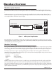
MaxxBass Overview MaxxBass System Overview MaxxBass can be utilized in almost any sound system to improve bass performance. The MaxxBass unit should be placed between either the mixer (for stereo) or low frequency crossover (for subwoofers) and the audio amplifier as shown in Figure 1. MaxxBass 101 supports stereo analog inputs and outputs with terminal blocks (with +4dBU sensitivity), XLR and TRS connections.
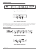
Front Panel Features Input Trim Knob Input Signal Indicators Bypass Button and Indicator MaxxBass Intensity MaxxBass Frequency Knob Knob Lock Button and Indicator Power Button and Indicator Figure 2. MaxxBass 101 Front Panel Input Trim Knob Input Signal Indicators MaxxBass Bypass Intensity Button Knob MaxxBass Bypass Lock Frequency Power Knob Indicators Figure 3. MaxxBass 102 Front Panel Both MaxxBass systems have a simple control interface requiring only a few control knobs and indicator LEDs.
MaxxBass includes stereo analog inputs and outputs designed for easy connection to most audio systems. The MaxxBass 101 supports stereo input and output with terminal block, XLR and TRS connections (+4dBu sensitivity), as shown in Figure 4. The MaxxBass 102 supports unbalanced RCA connector at -10dBu sensitivity as shown in Figure 5. Both MaxxBass 101 and MaxxBass 102 support an RS232 serial connector on their rear panel for future updates.
6 MaxxBass User Guide
Setting MaxxBass Controls The MaxxBass systems have only a few simple controls, but establishing the proper setting is critical to achieving the desired system performance. The description included explains the operation and provides some recommendations. It is required that a few minutes of listening tests are performed to insure that the controls are set for optimum performance. Step 1: Setting input level Input Trim Knob Input level should be set first.
amp amp A F f1 f2 f3 f4 f5 freq B F f1 f2 f3 f4 f5 freq Figure 6. Harmonics series at low and high Intensity settings Step 3: Verifying the settings and Locking Bypass The front of both MaxxBass systems includes a Bypass button. When the Bypass button is pressed, the MaxxBass unit turns off the MaxxBass processing. MaxxBass will attenuate the audio signal while in bypass by the setting on the input trim control. When in Bypass the Bypass LED will light.
Application Examples Small Speaker Systems MaxxBass significantly enhances audio systems with small speakers such as PA in restaurants and retail as shown in Figure 7. These systems, equipped with small or ceiling mount speakers, will be dramatically enhanced by allowing listeners to enjoy the deep bass tones in music without adding a subwoofer. It will eliminate system distortion caused by trying to push the PA Public Address System to deliver frequencies its speakers cannot reproduce.
Sound Reinforcement - Subwoofer Arrays Large scale subwoofer arrays with full range bass also benefit from MaxxBass to increase the bass and richness. This can allow a reduction in the number of amplifiers and subwoofers to reach the desired bass level. As shown in Figure 9, connect MaxxBass between the crossover and the subwoofer amplifier on the subwoofer path.
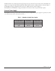
Specifications Technical Specifications MaxxBass 101 Input: Type Impedance Max Level Gain Range Output: Type XLR - Active balanced; Pin 2 hot Wire Terminal - Active balanced 1/4 TRS - Active balanced/unbalanced 10kΩ +22dBu -Inf - 1:1 ratio XLR - Active balanced; Pin 2 hot Wire Terminal - Active balanced 1/4 TRS - Active balanced/unbalanced Impedance 60Ω Max Level +22dBu @ 600Ω Freq Response (bypass) 20Hz-20kHz +0.2/-0.
Architectural Specifications for MaxxBass 102 The psycho-acoustic bass extension system shall be a two-channel unit with controls for Input Trim, (effect) Frequency, and (effect) Intensity. Front panel LEDs shall provide indication of signal presence, independently for left and right channels, Bypass, Lock, and Power (on). The rear panel shall provide a lock button, which disables the Frequency and Intensity front panel functions, effectively locking in the current settings.
14 MaxxBass User Guide