
Manual
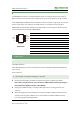
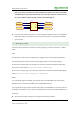
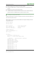


Table Of Contents

RS485 CAN Shield User Manual
3
Rev: V1.4, Date: May 19
th
2015
share awesome hardware
1. Hardware Description
1.1. Chip Pins Feature
1.1.1. MAX3485
The MAX3485 is 3.3V low-power transceivers for RS-485 communication. Each part contains one
driver and one receiver. RS-485 work under single power supply and communicate with half-duplex
mode.
MAX3485
Pin
Name
Function
1
RO
Receiver Output.
2
RE
Receiver Output Enable
Active LOW
3
DE
Driver Output Enable
Active HIGH
4
DI
Driver Input
5
GND
Ground Connection
6
A
Driver Output/Receiver Input.
Non-inverting
7
B
Driver Output/Receiver Input. Inverting
8
V
CC
Table 1: Transmit Function Truth Table
Inputs
Outputs
RE
DE
DI
Line Condition
B
A
X
1
1
No Fault
0
1
X
1
0
No Fault
1
0
X
0
X
X
Z
Z
Table 2: Receive Function Truth Table
Inputs
Outputs
RE
DE
A-B
RO
0
0
> +0.2V
1
0
0
< -0.2V
0
0
0
Inputs Open
1
1
0
X
Z
RO 1
RE 2
DE 3
DI 4
8 V
CC
7 B
6 A
5 GND
D
R
SP485
Top View