
Manual
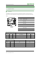
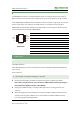
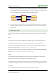
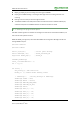


Table Of Contents

RS485 CAN Shield User Manual
4
Rev: V1.4, Date: May 19
th
2015
share awesome hardware
1.1.2. SN65HVD230
The SN65HVD230 controller area network (CAN) transceivers are designed by Texas Instruments. It
applies to CAN bus serial communication of higher speed, anti-jamming capability and high reliability.
On the SN65HVD230, pin 8(Rs) provides three different modes of operation: high-speed, slope control,
and low-power modes. The sending pin Tx of CAN controller is connected to Driver input (D) of
SN65HVD230. It sends the CAN node data to the CAN network. The receiving pin Tx of CAN controller
is connected to Receiver output (R) of SN65HVD230.
Top View
SN65HVD230
NO.
NAME
DESCRIPTION
1
D
Driver input
2
GND
Ground
3
V
CC
Supply voltage
4
R
Receiver output
5
V
ref
Reference output
6
CANL
Low bus output
7
CANH
High bus output
8
Rs
Standby/slope control
2. How to use
2.1. Preparations
Two RS485 CAN Shield
Two STM32 development board, we use Waveshare Xnucleo-F103RB board (with STM32F103R chip)
in this manual.
Some jumper wire.
2.2. Description of Jumper settings on Xnucleo
D14 (PB_9) and D15 (PB_8) are CAN's sending and receiving port respectively as default.
Note: please remap PB_9 and PB_8 to the function of STM32 CAN1 by modifying the program:
GPIO_PinRemapConfig(GPIO_Remap1_CAN1, ENABLE);
D7(PA_8) is for RS485 sending or receiving enable. High level is for sending, low level is for
receiving.
D8(PA_9), D2(PA_10) are the sending and receiving port of UART1. D0(PA_2), D1(PA_3) are the
sending and receiving port of UART2. You can choose UART1 or UART2 for RS485 transceiver
port by setting jumper 485 RXD/TXD JMP.
D
GND
V
CC
R
R
S
CANH
CANL
V
ref
1
2
3
4
8
7
6
5