
Manual
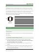
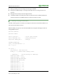


Table Of Contents

RS485 CAN Shield User Manual
5
Rev: V1.4, Date: May 19
th
2015
share awesome hardware
Note: PA_2 and PA_3 of Xnucleo are Serial to USB ports as default. If you want use D0 and D1
as RS485 serial port, the jumper JP4 should be set: connect pin 1 and pin 3, connect pin 2 and
pin 4. The schematic of JP4 on Xuncleo is shown in the following figure:
Communication between two boards: connect the CANH and CANL to another one’s CANH and
CANL of the CAN port separately. Connect the A and B to another one’s A and B of the RS485
port separately.
2.3. Working principl e
The demo program, divided into sending and receiving program, is based on mbed frame + STM32
library.
CAN:
The CAN driver is written based on STM32 library, packaged into the two file CAN.cpp and CAN.h.
At the beginning of the program, function CAN_Config() is called to initiate related registers.
At the side of sending program, the message to be sent will be saved into the Mailbox TxMessage,
then it will be sent by calling CAN_Transmit(CAN1, &TxMessage).
At the side of receiving program, the message received will be saved into the Mailbox RxMessage by
calling CAN_Receive(CAN1, CAN_FIFO0, &RxMessage).
RS485:
The sending side program sets RS485_E to high level, which will make RS485 into sending status.
Messages will be sent by function RS485.printf, through RS485 serial port.
The receiving side program enables reception interruption, and sets RS485_E to low level, which will
set RS485 to receiving status. Then, RX interrupt handler will scan received message via RS485.scanf.
Connection:
D14 and D15 are CAN's sending and receiving port respectively as default.
TXD RXD
PA 3/RX PA 2/T X
D0 /RX D1 /T X1
3
5
7
2
4
6
8
JP 4
H eader 4X2
PA 9/T XPA 10/RX