
Product Specifications

3.5 MCU Interface
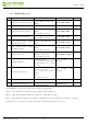
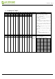
3.5-1) MCU interface selection
The 2.13inch e-Paper can support 3-wire/4-wire serial peripheral interface. In the
Module, the MCU interface is pin selectable by BS1 pins shown in.
T
able 3.5-1: MCU interface selection
B
S1 M
P
U I
nt
e
r
fa
c
e
L
4-lines serial periph
eral interface (SPI)
H 3-lines serial perip
heral interface (SPI) - 9 bits SPI
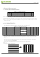
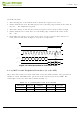
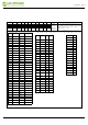
3.5-2) MCU Serial Peripheral I
nterface (4-wire SPI)
The 4-wire SPI consists of seria
l clock SCL, serial data SDA, D/C# and CS#,The
control pins status in 4-wire SPI in writing command/data is shown in Table 7- 2and the
write procedure 4-wire SPI is shown in Figue 7-2.
Table 3.5-2 : Control pins status of 4-wire SPI
Function SCL pin SDA pin D/C# pin CS# pin
Write
↑
Command bit
L
L
Write data
↑
Data bit H
L
Note:
(1) L is connected t
o VSS and H is connected to VDDIO
(2) ↑ stands for rising edge of signal
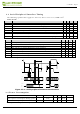
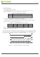
In the write mode, SDA is shifted into an 8-bit shift register on each rising edge of SCL in
the order of D7, D6, ... D0. The level of D/C# should be kept over the whole byte. The
data byte in the shift register is written to the
Graphic Display Data R
AM (RAM)/Data
Byte register or command Byte register according to D/C# pin.
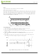
Figure 3.5-1: Write procedu
re in 4-wire SPI mode
2.13inch e-Paper
www.waveshare.com
14/39