
Specification

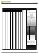
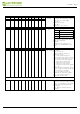
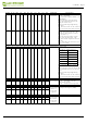
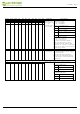
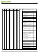

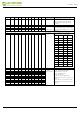
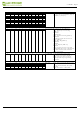
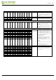
Table Of Contents

R/W# D/C# Hex D7 D6 D5 D4 D3 D2 D1 D0 Command
Description
0
0
0F
0
0
0
0
1
1
1
1
Gate scan start
position
Set the sc
anning start position of the
gate
driver. The valid
range is from 0
to 295.
A[8:0] = 000h [POR]
W
hen TB=0:
SCN [8:0] = A[8:0]
When TB=1:
SCN [8:0] = 295 - A[8:0]
0
1
A7 A6 A5 A4 A3 A2 A1 A0
0
1
0
0
0
0
0
0
0
A8
0
0
10
0
0
0
1
0
0
0
0
Deep Sleep
mode
Deep Sleep mode C
ontrol:
A[1:0]
:
Description
00
Normal
Mode
[POR]
01
Enter
Deep
Sleep
Mode
1
11
Enter
Deep
Sleep
Mode
2
After this comma
nd initiated, the chip
will
enter Deep Sleep Mod
e, BUSY pad
will
keep output high.
Rema
rk:
To
Exit Deep Sleep mod
e, User
required
to send HWRESET
to the
driver
0
1
0
0
0
0
0
0
A1 A0
0
0
11
0
0
0
1
0
0
0
1
Data Entry
mode
setting
Define da
ta entry sequence
A[2:0] =
011 [POR]
A [1:0
] = ID[1:0]
Address automatic increment /
decrement
setting
The se
tting of incrementing or
decrementing of t
he address counter
can
be made independe
ntly in each
upper and
lower bit of the add
ress.
00 –Y decrement, X dec
rement,
01 –Y decrement, X incr
ement,
10 –Y increment, X de
crement,
11 –Y increment, X increment [POR]
A[2] = AM
Set the direct
ion in which the address
counter is upda
ted automatically after
data
are
wri
t
t
e
n
t
o
t
h
e RA
M
.
A
M= 0, the address counter is
updated in
the X direction. [PO
R]
AM = 1, the address counter is
updated in
the Y direction.
0
1
0
0
0
0
0
A2 A1 A0
0
0
12
0
0
0
1
0
0
1
0
SW RESET It resets the
commands and
parameters to
their S/W Reset def
ault
values except
R1
0
h-D
e
ep
S
l
eep M
o
de
D
u
r
in
g operation, BUSY pad will
output
high.
Note: RAM are u
naffected by this
command.
2.13inch e-Paper
www.waveshare.com
23/39