SPECIFICATION Product Type : EPD Model Number : 7.5inch e-Paper (B) Description : Screen Size: 7.5" Color: Black, White and Red Display Resolution: 640*385 Waveshare Electronics Waveshare Electronics Room 813, Dynamic World Building, Zhenhua Rd, Futian District, Shenzhen China Website: www.waveshare.
7.5inch e-Paper (B) Revision History Rev. Issued Date Revised Contents 1.0 Jul.01.2015 Preliminary 1.1 Aug.17.2015 1. In part 12: Delete block diagram. 1.2 Sep.21.2015 1. Modify Module Name 1.3 Nov.04.2015 1. In part 11: Modify T=+40℃, RH=80% for 168 hrs to 240 hrs. 2.0 Mar.01.2017 1. In part 7-5): Modify Reference Circuit. www.waveshare.
7.5inch e-Paper (B) TECHNICAL SPECIFICATION CONTENTS NO.
7.5inch e-Paper (B) 1. Over View The display is a TFT active matrix electrophoretic display, with interface and a reference system design. The 7.5” active area contains 640×384 pixels, and has 3-bit white/black/red full display capabilities. An integrated circuit contains gate buffer, source buffer, interface, timing control logic, oscillator, DC-DC, SRAM, LUT, VCOM and border are supplied with each panel. 2.
EPD PS FPL AA 4. Mechanical Drawing of EPD module 0.8 0 2.70 1.70 www.waveshare.com 170.20±0.20 166.80±0.20 164.80±0.20 163.20±0.10 1.70 2.70 0.80 97.92±0.10 AA 104.09±0.20 FPL 106.09±0.20 PS 111.20±0.20 EPD 77.80±0.20 75.13±0.20 79.90±0.20 24.00 0.20 ± 73.03±0.20 0.255 (rtv area) 1.35 max 1.18±0.1 (without protective film) (ec area) 1.33 max 0.25 5 PS FPL 1.5max RTV EC IC GLASS EPD thickness (section drawing) 1,Unlabeled tolerances:±0.
5.
as data. When the pin is pulled Low, the data will be interpreted as command. Note 5-3: This pin (RES#) is reset signal input. The Reset is active Low. Note 5-4: This pin (BUSY) is Busy state output pin. When Busy is low the operation of chip should not be interrupted and any commands should not be issued to the module.
6.
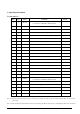
# Command W/R C/D D7 D6 D5 D4 D3 D2 D1 D0 0 0 0 0 1 0 0 0 1 1 23h 0 0 0 0 1 0 0 1 0 0 24h 0 0 0 0 1 0 0 1 0 1 25h 0 0 0 0 1 0 0 1 1 0 26h 0 0 0 0 1 0 0 1 1 1 27h 0 0 0 0 1 0 1 0 0 0 28h 0 0 0 0 1 0 1 0 0 1 29h 0 0 0 0 1 1 0 0 0 0 30h 0 1 - - # # # # # # 0 0 0 1 0 0 0 0 0 0 1 1 # # # # # # # # D[10:3]/TS[7:1] 00h 1 1 # # # - - - - - D[2:0]/TS[0] 00h 0 0 0 1 0 0
# Command 29 30 31 32 33 TCON Setting (TCON) TCON resolution (TRES) SPI flash control (DAM) Revision(REV) W/R C/D D7 D6 D5 D4 D3 D2 D1 D0 0 0 0 1 1 0 0 0 0 0 0 1 # # # # # # # # 0 0 0 1 1 0 0 0 0 1 0 1 # # # # # # # # 0 1 - - - - - - # # 0 1 - - - - - - - # 0 1 # # # # # # # # 0 0 0 1 1 0 0 1 0 1 0 1 - - - - - - - # 0 0 0 1 1 1 0 0 0 0 0 1 - - # # # # # # 0 0 0 1 1 1 0
1) Panel Setting (PSR) (R00H) Action Setting the panel W/R C/D D7 D6 D5 D4 D3 D2 D1 D0 0 0 0 0 0 0 0 0 0 0 0 1 RES1 RES0 LUT_EN - UD SHL SHD_N RST_N RES[1:0]: Display resolution setting (source×gate) 00b: 640×480 (default) 01b: 600×450 10b: 640×448 11b: 600×448 LUT_EN: LUT selection 0: Using LUT from external Flash. 1: Using LUT from register. UD: Gate Scan Direction 0: Scan down 1: Scan up. (default) Gn SHL: Source shift direction 0: Shift left.
0: 3-bit data mode for pure driver 1: 2-bit data mode for pure driver (default) Vsource_LV_EN: VSource LV power selection. 0: External source power from VSH_LV and VSL_LV pin. 1: Internal DCDC function for generate source power. (default) VSource_EN: VSource power selection. 0: External source power from VSH and VSL pin. 1: Internal DCDC function for generate source power. (default) VGate_EN: VGate power selection. 0: External gate power from VGH and VGL pin.
will keep until VDD off. SD output and VCOM will base on previous condition. It may have two conditions: 0v or floating. 4) Power OFF Sequence Setting(PFS) Action Setting Power OFF Sequence T_VDS_OFF[1:0]: (R03H) W/R C/D D7 D6 D5 D4 D3 D2 D1 D0 0 0 0 0 0 0 0 0 1 1 0 1 - - T_VDS_OFF[1:0] - - - - Power OFF Sequence of VDH and VDL.
8) Data Start Transmission 1 (DTM1) (R10H) Action Starting data transmission W/R C/D D7 D6 D5 D4 D3 D2 D1 D0 0 0 0 0 0 1 0 0 0 0 0 1 Dummy KPixel12 KPixel11 KPixel10 Dummy KPixel22 Kpixel21 Kpixel20 0 1 .. .. .. .. .. .. .. .. 0 1 Dummy Kpixel Kpixel Kpixel Dummy Kpixel Kpixel Kpixel (2M-1)2 (2M-1)1 (2M-1)0 (2M)2 (2M)1 (2M)0 This Command indicates that user starts to transmit data. Then write to SRAM.
applying new gray level waveform. IP_EN: Image process enable. 0: No action. 1: Image process enable (auto return to ‘0’ after image process is finished. IP_SEL[2:0]: Image process selection.
This command builds LUTG1. 16) Gray2 LUT (LUTG2) Action (R24H) W/R C/D 0 0 D7 D6 D5 D4 D3 D2 D1 D0 Build Look-Up Table for Gray2 (261-byte command, bytes 2~14 0 0 1 0 0 1 0 0 repeated 20 times) This command builds LUTG2. 17) Red0 LUT (LUTR0) (R25H) Action W/R C/D 0 0 D7 D6 D5 D4 D3 D2 D1 D0 Build Look-Up Table for Red0 (261-byte command, bytes 2~14 0 0 1 0 0 1 0 1 repeated 20 times) This command builds LUTR0.
21) XON LUT (LUTXON) Action (R29H) W/R C/D 0 0 D7 D6 D5 D4 D3 D2 D1 D0 Build Look-Up Table for XON (201-byte command, bytes 2~11 0 0 1 0 1 0 0 1 repeated 20 times) This command builds LUTXON. 22) PLL Control (PLL) (R30H) Action W/R C/D D7 D6 D5 D4 D3 D2 D1 D0 0 0 0 0 1 1 0 0 0 0 0 1 - - Controlling PLL M[2:0] N[2:0] The command controls the PLL clock frequency.
This command reads the temperature sensed by the temperature sensor. TS[7:0]: When TSE (R41h) is set to 0, this command reads internal temperature sensor value. D[10:0]: When TSE (R41h) is set to 1, this command reads external LM75 temperature sensor value. Bit 7~0 Temperature(℃) 0000 0000b 0 0000 0001b 0.5 0000 0010b 1 .. .. 0101 1010b 45 .. .. 0110 0100b 50 .. .. 1100 1110b -25 .. .. 1111 1110b -1 1111 1111b -0.5 BUSY become low after TSC command.
00: 1 byte (head byte only) 01: 2 bytes (head byte + pointer) 10: 3 bytes (head byte + pointer + 1stparameter) 11: 4 bytes (head byte + pointer + 1stparameter + 2nd parameter) D[5:3]: User-defined address bits (A2, A1, A0) D[2:0]: Pointer setting WMSB[7:0]: MSByte of write-data to external temperature sensor WLSB[7:0]: LSByte of write-data to external temperature sensor.
… … … … 0110 11 1110 3 0111 10(Default) 1111 2 28) Low Power Detection(LPD) (R51h) Action W/R C/D D7 D6 D5 D4 D3 D2 D1 D0 0 0 0 1 0 1 0 0 0 1 1 1 - - - - - - - LPD Detect Low Power This command indicates the input power condition. Host can read this flag to learn the battery condition. LPD: Internal temperature sensor switch 0: Low power input (VDD<2.
30) Resolution Setting(TRES) Action Set Display Resolution (R61H) W/R C/D D7 D6 D5 D4 D3 D2 D1 D0 0 0 0 1 1 0 0 0 0 1 0 1 0 1 0 1 0 1 HRES[7:0] - - - - - - HRES[9:8] VRES[7:0] - - - - - - - VRES[8] This command defines alternative resolution and this setting is of higher priority than the RES[1:0] in R00H (PSR). HRES[9:0]: Horizontal Display Resolution VRES[8:0]: Vertical Display Resolution Resolution setting (R61H) has higher priority than RES[1:0] (R00H).
32) Revision(REV) (R70H) Action W/R C/D D7 D6 D5 D4 D3 D2 D1 D0 0 0 0 1 1 1 0 0 0 0 1 1 LUTVER[7:0] 1 1 LUTVER[15:8] 1 1 LUT/Chip Revision 0 0 0 0 CHREV[3:0] The LUTVER[15:0] is read from OTP address = 25001 and 25000. LUTVER[15:0]: LUT versionL. CHREV [3:0]: Chip Revision.
35) VCOM Value(VV) (R81h) Action W/R C/D D7 D6 D5 D4 D3 D2 D1 D0 Automatically 0 0 1 0 0 0 0 0 0 1 measure vcom 1 1 - VV [6:0] This command gets the Vcom value. VV[6:0]: Vcom Value Output VV[6:0] Vcom value 000 0000b 0V 000 0001b -0.05 V 000 0010b -0.10 V 000 0011b -0.15 V : : 101 0000b -4.00 V (Others) -4.
7. Electrical Characteristics 7-1) Absolute maximum rating Parameter Symbol Rating Unit Logic Supply Voltage VCI -0.3 to +6.0 V Logic Input Voltage VIN -0.3 to VCI +0.3 V Operating Temp. range TOPR 0 to +40 ℃ Storage Temp. range TSTG -25 to +60 ℃ 7-2) Panel DC Characteristics The following specifications apply for: VSS = 0V, VCI = 3.3V, TA = 25℃ Parameter Symbol Conditions Min Typ Max Unit Single ground VSS - - 0 - V Logic Supply Voltage VCI - 2.3 3.3 3.
7-3) Panel AC Characteristics 7-3-1) MCU Interface 7-3-1-1) MCU Interface Selection In this module, there are 4-wire SPI and 3-wire SPI that can communicate with MCU. The MCU interface mode can be set by hardware selection on BS1 pins. When it is “Low”, 4-wire SPI is selected. When it is “High”, 3-wire SPI (9 bits SPI) is selected.
7-3-1-2) MCU Serial Interface (4-wire SPI) The 4-wire SPI consists of serial clock SCLK, serial data SDIN, D/C#, CS#. In SPI mode, D0 acts as SCLK, D1 acts as SDIN. Function CS# D/C# SCLK Write Command L L ↑ Write data L H ↑ Table 7-4-1-2: Control pins of 4-wire Serial Peripheral interface Note 7-4: ↑stands for rising edge of signal SDIN is shifted into an 8-bit shift register in the order of D7, D6, ... D0.
7-3-1-3) MCU Serial Interface (3-wire SPI) The 3-wire serial interface consists of serial clock SCLK, serial data SDIN and CS#. In 3-wire SPI mode, D0 acts as SCLK, D1 acts as SDIN, The pin D/C# can be connected to an external ground. The operation is similar to 4-wire serial interface while D/C# pin is not used. There are altogether 9-bits will be shifted into the shift register on every ninth clock in sequence: D/C# bit, D7 to D0 bit.
7-3-2) Timing Characteristics of Series Interface Symbol Signal Parameter Min Typ Max Unit Chip Select Setup Time 60 - - ns Chip Select Hold Time 65 - - ns Chip Select Setup Time 20 - - ns tchw Chip Select Setup Time 40 - - ns tscycw Serial clock cycle (write) 100 - - ns tshw SCL “H” pulse width (write) 35 - - ns SCL“L” pulse width (write) 35 - - ns Serial clock cycle (Read) 150 - - ns tshr SCL “H” pulse width (Read) 60 - - ns tslr SCL “L” pulse widt
7-4) Power Consumption Parameter Symbol Conditions TYP Max Unit Remark Panel power consumption during update - 25℃ 26.4 40 mW - Power consumption in standby mode - 25℃ - 0.0165 mW - 7-5) Reference Circuit Figure. 7-5(1) Figure. 7-5(2) www.waveshare.
8. Typical Operating Sequence 8-1) Normal Operation Flow 1. LUT from register System power Reset the EPD driver IC Booster soft start Power setting Power on Flash enable Turn off the flash Flash disable Panel setting PLL control Resolution setting Load image data Display refresh Turn off Enter into deep sleep mode www.waveshare.
2. LUT from flash System power Reset the EPD driver IC Booster soft start Power setting Power on Panel setting PLL control Resolution setting Define the flash Load image data Display refresh Flash enable Turn off the flash Flash disable Turn off Enter into deep sleep mode www.waveshare.
8-2) Reference Program Code 1.
2.
9. Optical characteristics 9-1) Specifications Measurements are made with that the illumination is under an angle of 45 degrees, the detection is perpendicular unless otherwise specified.
9-3) Reflection Ratio The reflection ratio is expressed as: R = Reflectance Factor white board x (L center / L white board) L center is the luminance measured at center in a white area (R=G =B=1). L white board is the luminance of a standard white board. Both are measured with equivalent illumination source. The viewing angle shall be no more than 2 degrees.
10. Handling, Safety and Environmental Requirement WARNING The display glass may break when it is dropped or bumped on a hard surface. Handle with care. Should the display break, do not touch the electrophoretic material. In case of contact with electrophoretic material, wash with water and soap. CAUTION The display module should not be exposed to harmful gases, such as acid and alkali gases, which corrode electronic components.
11. Reliability test TEST CONDITION T = 40℃, 1 METHOD REMARK When the experimental cycle finished, the EPD samples When experiment will finished, the EPD be taken out from the high High-Temperatu RH=35%, temperature environmental chamber and set aside for a few must meet electrical re Operation for 240 hrs minutes.
pattern is 30 minutes. After 30 minutes, it needs 30min to let standards. temperature rise to -25 ℃ . One temperature cycle (2hrs) is complete. 2. Temperature cycle repeats 70 times. 3. When 70 cycles finished, the samples will be taken out from experiment chamber and set aside a few minutes. As EPDs return to room temperature, tests will observe the appearance, and test electrical and optical performance based on standard # IEC 60068-2-14NB.
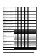
12. Point and line standard Shipment Inseption Standard Part-A:Active area Part-B:Border area Equipment:Electrical test fixture, Point gauge Outline dimension: 170.2(H)×111.2(V)×1.18(D) Unit:mm Temperature Environment 23±2℃ Name Humidity Illuminance 55± 1200~ 5%RH 1500Lux Causes protection sheet, Spot 300 mm 35 Sec Part-A 0.25mm 0.4mm 4 0.4mm < D ≤ 0.5mm 1 0.5mm < D Length Width Part-A Scratch on FPL or L ≤ 2.0mm W≤ 0.2 mm Ignore sheet. 2.0 mm < L≤ 8.0mm 0.2 mm
13. Packing empty tray 2 6 3 vacuum bag 1 3 2nd layer 1st layer 4 4 2 2 1 2 4 3 tape 4(PCS)×12(Layer)=48PCS 1150mm 7550mm total 12 layer Protector 9000mm Pallet PP belt 48(PCS)×16(BOX)=768PCS www.waveshare.