
Data Sheet

www.waveshare.com
19/40
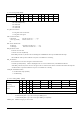
00: 1 byte (head byte only)
01: 2 bytes (head byte + pointer)
10: 3 bytes (head byte + pointer + 1
st
parameter)
11: 4 bytes (head byte + pointer + 1
st
parameter + 2
nd
parameter)
D[5:3]: User-defined address bits (A2, A1, A0)
D[2:0]: Pointer setting
WMSB[7:0]: MSByte of write-data to external temperature sensor
WLSB[7:0]: LSByte of write-data to external temperature sensor.
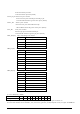
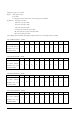
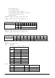
26) Temperature Sensor Read (TSR) (R43H)
Action
W/R
C/D
D7
D6
D5
D4
D3
D2
D1
D0
Temperature Sensor Selection
0
0
0
1
0
0
0
0
1
1
1
1
RMSB[7:0]
1
1
RLSB[7:0]
This command could read data from the external temperature sensor.
RMSB[7:0]: MSByte of read-data from external temperature sensor.
RLSB[7:0]: LSByte of read-data from external temperature sensor.
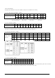
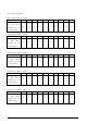
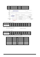
27) VCOM and Data Interval Setting(CDI) (R50H)
Action
W/R
C/D
D7
D6
D5
D4
D3
D2
D1
D0
Set Interval between
Vcom and Data
0
0
0
1
0
1
0
0
0
0
0
1
VBD[2:0]
DDX
CDI[3:0]
This command indicates the interval of Vcom and data output. When setting the vertical back porch, the total blanking will be kept (20
Hsync).
VBD[2:0]: Border output selection.
DDX: Data polality.
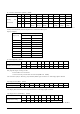
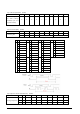
The mapping table of VBD[2:0] and DDX is listed as below.
Border Output
VBD[2:0]
DDX=1(default)
DDX=0
LUT
LUT
000
Black
White
001
Gray1
Gray2
010
Gray2
Gray1
011
White
Black
100
Red0
Floating
101
Red1
Red2
110
Red2
Red1
111
Floating
Red0
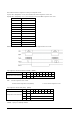
CDI[3:0]: Vcom and data interval
CDI[3:0]
Vcom and Data Interval
CDI[3:0]
Vcom and Data Interval
0000b
17 hsync
1000
9
0001
16
1001
8
0010
15
1010
7