
Data Sheet


www.waveshare.com
7/40
as data. When the pin is pulled Low, the data will be interpreted as command.
Note 5-3: This pin (RES#) is reset signal input. The Reset is active Low.
Note 5-4: This pin (BUSY) is Busy state output pin. When Busy is low the operation of chip should not be interrupted and any commands
should not be issued to the module. The driver IC will put Busy pin low when the driver IC is working such as:
- Outputting display waveform; or
- Communicating with digital temperature sensor
Note 5-5: This pin (BS1) is for 3-line SPI or 4-line SPI selection. When it is “Low”, 4-line SPI is selected. When it is “High”, 3-line SPI (9
bits SPI) is selected. Please refer to below Table.
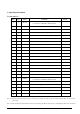
Table: Bus interface selection
BS1
MPU Interface
L
4-lines serial peripheral interface (SPI)
H
3-lines serial peripheral interface (SPI) – 9 bits SPI