
User Guide

Operation
2018 Microchip Technology Inc. DS50002751C-page 17
2.3 TARGET COMMUNICATION CONNECTIONS
2.3.1 Standard Communication Target Connections
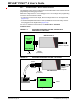
2.3.1.1 USING SINGLE IN-LINE CONNECTOR
Use the single in-line connector between the MPLAB PICkit 4 In-Circuit Debugger and
the target board connector (see Figure 2-1 and Section B.3 “Communication
Hardware”).
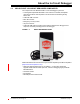
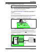
2.3.1.2 USING AN ADAPTER
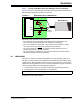
Use the AC164110 adapter between the MPLAB PICkit 4 In-Circuit Debugger and the
target device with the modular interface (six conductor) cable. The pin numbering for
the connector is shown from the bottom of the target PCB in Figure 2-3.
FIGURE 2-3: STANDARD RJ-11 CONNECTION AT TARGET
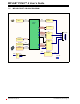
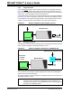
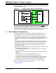
2.3.2 Target Connection Circuitry
Figure 2-4 shows the interconnections of the MPLAB PICkit 4 In-Circuit Debugger to
the connector on the target board. The diagram also shows the wiring from the
connector to a device on the target PCB. A pull-up resistor (usually around 10-50 k)
is recommended to be connected from the V
PP/MCLR line to VDD so that the line may
be strobed low to reset the device.
FIGURE 2-4: STANDARD CONNECTION TO TARGET CIRCUITRY
Note: Refer to the data sheet for the device you are using as well as the applica-
tion notes for the specific interface for additional information and diagrams.
1
2
3
4
5
6
Target
Connector
Target
Bottom Side
PCB
VPP/MCLR
Vss
PGC
V
DD
PGD
LVP
VDD
VPP/MCLR
PGC
PGD
V
SS
AVDD
AVSS
2
1
5
4
3
User Reset
Interface
Connector
Application
PCB
Device
MPLAB PICkit 4
10-50k