
Specifications


301/302 User Manual
Input and Output
Connectors
The Model 301/302 has 6 or 9 BNC connectors on its front panel: one
main output and one auxiliary output per channel, one SYNC output,
one AM input per channel, one trigger input and one sample clock
input.
Main Output -
Channel A
The channel A output connector outputs fixed (standard) waveforms
to 150 MHz, user (arbitrary) and sequenced waveforms with sampling
clock to 300 MS/s. Output impedance is 50Ω, that is, the cable
connected to this output should be terminated with 50Ω. Output
amplitude accuracy is calibrated when connected to a 50Ω load. The
output amplitude is doubled when the output impedance is above 1
MΩ.
Auxiliary Output -
Channel A (I)
The Auxiliary output connector outputs exactly the same waveforms
as the Main output connector. The only difference is that the low
output has fixed amplitude of 1 Vp-p into 50Ω
Main Output -
Channel B
The Channel B output connector outputs fixed (standard) waveforms
to 150 MHz, user (arbitrary) and sequenced waveforms with sampling
clock to 300 MS/s. Output impedance is 50Ω, that is, the cable
connected to this output should be terminated with 50Ω. Output
amplitude accuracy is calibrated when connected to a 50Ω load. The
output amplitude is doubled when the output impedance is above 1
MΩ.
Auxiliary Output -
Channel B (Q)
The Channel B Auxiliary output connector outputs exactly the same
waveforms as the Main output connector. The only difference is that
the low output has fixed amplitude of 1 Vp-p into 50Ω
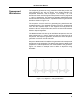
SYNC Output
The SYNC output generates a single TTL pulse for synchronizing
other instruments (i.e., an oscilloscope) to the output waveform. The
SYNC signal always appears at a fixed point relative to the waveform.
The location of the signal along the waveform is programmable.
Trigger Input
In general, the trigger input accepts signals that stimulate the output
waveforms. The trigger input is inactive when the generator is in
Getting Started
5