OPERATION MANUAL MODEL 3HRV HEADEND REVERSE SWEEP RECEIVER This document contains information proprietary to Wavetek. The information in this document is not to be used or duplicated in any manner without the prior approval, in writing, of Wavetek. Wavetek CATV Division 5808 Churchman Bypass Indianapolis, IN 46203-6109 (800)851-1198 (317)788-5960 Fax: (317)782-4607 E-Mail: catvsupport@wavetek.com Internet: http://www.wavetek.com 11/96 Rev. A Manual Part No.
WARRANTY Wavetek warrants that all Products manufactured or procured by Wavetek conform to Wavetek’s published specifications and are free from defects in materials and workmanship for a period of one (1) year from the date of delivery to the original Buyer, when used under normal operating conditions and within the service conditions for which they were designed. This warranty is not transferrable and does not apply to used or demonstration products.
Contents SECTION 1 - GENERAL INFORMATION 1.1 INTRODUCTION ................................................................ 1-1 1.2 SPECIFICATIONS ............................................................. 1.2.1 Frequency .................................................................... 1.2.2 Level Measurement ................................................... 1.2.3 Hum Measurement ..................................................... 1.2.4 Carrier to Noise Measurement ................................
2.8 WORLDWIDE SALES OFFICES .....................................2-5 SECTION 3 - USER INTERFACE 3.1 INTRODUCTION .............................................................. 3-1 3.2 FRONT-PANEL DESCRIPTION ................................... 3-1 3.2.1 Soft Keys ...................................................................... 3-1 3.2.2 Measurement Mode Selection Keys ......................... 3-2 3.2.3 Support Mode Selection Keys ................................... 3-3 3.2.4 Arrow Keys ..............
4.7 HOW TO MEASURE C/N ................................................ 4-43 4.8 HOW TO MEASURE HUM ............................................. 4-45 4.9 MODULATION ................................................................. 4-46 4.10 SPECTRUM ANALYZER MODE ................................ 4-47 4.11 SWEEP MODE ................................................................. 4-52 4.12 FILE .................................................................................... 4-54 4.12.
MODEL 3HRV SECTION 1 GENERAL INFORMATION 1.1 INTRODUCTION The 3HRV Reverse Sweep Receiver is a headend rack mounted unit that handles the reverse sweep job for up to 10 different technicians on the same cluster of nodes. The addition of the 3HRV to the Wavetek Sweep System takes the responsibility of the reverse sweep away from the 3ST. This serves to speed up the reverse sweep rate.
The 3HRV is a full-featured signal analysis meter, with a complete spectrum display and an analog representation of single channel measurement data. When tuned to a specific channel, a comprehensive set of information is provided: tuned channel, video frequency and level, audio frequency and level, the difference between video and audio carrier levels. The 3HRV is a standard 19" rack mount unit, that weighs approximately fifteen pounds.
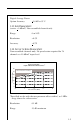
Digital Average Power Option Accuracy: +1.8 dB at 25°C 1.2.3 Hum Measurement (carrier > 0 dBmV) Non-scrambled channels only Range: 0 to 10% Resolution: <0.2% Accuracy: +0.7% 1.2.4 Carrier to Noise Measurement Non-scrambled channels only. No preselection required for 78 channels at +10 dBmV input level. Carrier to Noise Ratio Depth of Measurement Characteristics * 60 Out of Measurement Range Carrier to Noise Range 50 40 30 uracy B Acc +3.0 d uracy B Acc +2.
1.2.5 Telemetry Frequency: User defined, 5 to 1,000 MHz Modulation: FSK, 100 kHz deviation Spectrum Required: »1 MHz recommended 1.2.6 Transmitter Frequency Range: 5 to 1,000 MHz Level Range: +20 to +50 dBmV; settable in 2 dB increments Spectral Purity: Hars -30 dBc; Spurs -35 dBc 1.2.7 Spectrum Mode Spans: 3, 5, 10, 20, and 50 MHz (0.3, 0.5, 1, 2, and 5 MHz/div) Sweep Rates: 2 seconds (50 & 5 MHz) Display Scaling and Range: Spurious Free Dynamic Range: 1-4 0.
1.2.8 Intermodulation Distortion CSO / CTB Characteristics * Depth of Measurement (dB) (without preamplification / with preselection) 60 Out of Measurement Range 50 40 30 y rac ccu BA 0d +3. y c BA 5d +2. ac cur 20 10 0 -20 -10 0 10 20 30 Video Signal Level (dBmV) *Typical Specifications Range: 60 dB maximum Resolution: 1 dB 1.2.9 Depth of Modulation Assumes presence of white reference on any VITS line. Nonscrambled channels only. Range: 80 to 100% Resolution: <0.5% at 85% 1.
Dimensions: 3HRV: 48.3 cm (W) x 13.3 cm (H) x 35.6 cm (D), 19" (W) x 5.25" (H) x 14" (D) Weight: 3HRV: 6.8 kg (15 lbs.) Operating Temperature Range: 0 to +50°C; 32 to 122°F 1.2.12 Powering Frequency 47 to 63 Hz ~ 100 VA Input Current: 1.2A @ 100 VAC. 0.5A @ 265 VAC. Fuse 1.25 A, 250V 5X20mm SLO-BLO (2 required) 1.2.13 Standard Accessories Line Cord Channel Plan Transfer Cable Operations Manual 1.2.
SBC-1 SBC-6 1217-50-0151 PP-75 PP-55-110 PP-110-220 PP-220-440 PP-440-880 7201 7202 7203 7204 Charger for one spare Stealth Battery Cartridge Charger for up to six spare Stealth Battery Cartridges Stealth Serial Printer Cable Precision Preselector for Carrier-To-Noise and Intermodulation Distortion Testing (55 to 440 MHz) Tunable Precision Preselector (55 to 110 MHz) Tunable Precision Preselector (110 to 220 MHz) Tunable Precision Preselector (220 to 440 MHz) Tunable Precision Preselector (440 to 880 MHz)
SECTION 2 INSTALLATION 2.1 INTRODUCTION This section provides information on how to install the 3HRV Headend Reverse Sweep Receiver. 2.2 UNPACKING AND INSPECTION The instrument was inspected, and given final operational and quality control tests prior to being carefully packaged for shipment. The unit should operate in accordance with the specifications listed in this manual. When unpacking the instrument, inspect the shipping container and instrument for shipping damage.
The transmitter output level is variable from +20 to +50 dBmV in 2 dB increments. The output level will be attenuated by the tap value of the directional coupler. For example, if a telemetry signal level of +16 dBmV is desired on the system and the output of the 3HRV is set to +36 dBmV, a directional coupler value of 20 dB may be used, or the combination of a lower value directional coupler and an attenuator pad.
2.5 POWER REQUIREMENTS The 3HRV operates on 90-265 VAC, 57-63 Hz single phase input power source. 2.6 CABLE SPECIFICATIONS There are two cables associated with the operation of the 3HRV; Stealth to Stealth, and a Serial Printer cable. The following information describes each of the associated cables. Stealth to Stealth The Stealth to Stealth cable, (1217-50-0149) provided with each 3HRV, is used for communications between Stealth units.
Serial Printer Cable The Serial Printer Cable, (1217-50-0151) can be used to print data directly from the 3HRV.
2.7 TECHNICAL SUPPORT We've worked hard to make the 3HRV as easy-to-use as possible. However, if you have a problem using your unit you can contact Wavetek's Technical Support for help. You can reach Wavetek's Technical Support, Monday through Friday between 8 am and 5 PM at (317) 788-5960. Wavetek also maintains a support forum on the Internet. You can leave messages and a Support Specialist will get back to you at Internet address: CATVSUPPORT@wavetek.com.
SECTION 3 USER INTERFACE 3.1 INTRODUCTION This section will help you become familiar with the front-panel controls of the Model 3HRV. Included are descriptions of the frontpanel and notes on the use of features. 3.2 FRONT-PANEL DESCRIPTION The hardware portion of the user interface consists of a 320x240 dot matrix LCD and a 40-key keypad. The keypad includes: • eight Soft keys • eight Measurement Mode selection keys • four Support Mode selection keys • four Arrow keys • sixteen Numeric Entry keys 3.2.
3.2.2 Measurement Mode Selection Keys Measurement modes are chosen by pressing the appropriate Measurement Mode Selection key. There is a key for each of the eight major measurement functions. These keys are located directly below the display. LEVEL: Signal level measurements on individual channels are made by entering a specific channel number and pressing the channel key. Measurements can also be made by selecting the carrier with a marker in the Scan mode and pressing the Level key.
SCAN: Use the Scan mode to get a good look at absolute carrier levels. In this mode a bar graph showing all carrier levels is displayed. SWEEP: This mode monitors the signals injected into vacant spectrum areas by the 3SRVs. Also, through telemetry transmits to the field current condition of noise and ingress to any 3SRV Receivers that are connected to the system. NOTE: Telemetry occurs only while the unit is in Sweep mode.
File: Allows the user to access measurement files. Auto: This function provides automated FCC 24 hour testing capabilities. Setup: The setup functions are used to set or adjust the operating parameters of the unit. Print: Allows the user to print the current measurement screen. 3.2.4 Arrow Keys The four Arrow keys are used for various purposes. There functions are described in the individual sections for each operating mode. These keys are located to the right of the Support Mode Selection keys.
3.2.5 Alpha-Numeric Entry Keys The Alpha-Numeric keys are used to enter data as needed during the operation of the unit. There are three indicators associated with keypad entry. These indicators appear in the title bar to the left of the time. The three are as follows: AB - alpha entry mode C 12 - numeric entry mode 3 - multiple choice mode Alpha Entry Mode Most numeric keys have alphabetic characters printed on them. These characters can be accessed when the alpha entry indicator appears in the title bar.
Numeric Entry Mode In the numeric entry mode, only the numerals 0 through 9 and the decimal point can be entered. When negative values are allowed, the FCN, +/- key sequence toggles between positive and negative entry. The numeric value may also be incremented and decremented using the UP and DOWN arrow keys. Numeric entry must be terminated by pressing the ENTER key. Multiple Choice Mode This mode allows you to sequence through a series of choices which appear in the edit box. 3.2.
SECTION 4 OPERATION - HOW TO USE THE 3HRV HEADEND REVERSE SWEEP RECEIVER 4.1 INTRODUCTION This section provides detailed operation of the 3HRV. Included are detailed descriptions of the various displays of the selected modes of operation. 4.1.1 Wavetek Stealth Reverse Sweep Concept With the reverse sweep option, a transmitter is built into the handheld sweep receiver. The headend reverse sweep receiver (3HRV) is set up to receive the reverse sweep sent from the field.
This is why it is best to transmit the sweep from the amplifier test point and measure it in the headend. This ensures that the system is properly aligned to carry signals in the reverse path. 4.1.3 Interfacing With Different Network Architectures Single Cable - Split Band Network The Model 3HRV is connected in the headend as shown in figure 1. The connections are similar to those made for forward sweep, with the monitor output connected to the combining network.
The directional coupler on the input side should be designed for at least the frequency range of the forward bandwidth of the network under test. (This coupler network should never be connected to the system without the 3SRV attached, or the resulting lack of isolation may cause signals from the forward path to bleed over to the reverse path.) Figure 2. Single Cable - Split Band Network Reverse Sweep Configuration With Directional Test Points.
Figure 3. Transmitter Connections In Headend For Hybrid Fiber/Coax Networks Figure 4. Fiber Node Test Point Connections Dual Cable Network Another possible, though rare, network configuration is the "Dual Cable Network", in which a full bandwidth is used for both forward and reverse - essentially two cable systems overlaying each other with signals carried in opposite directions. These networks are impossible to sweep simultaneously in both directions with one man.
The problem is that the two systems use the same spectrum, making it impossible to distinguish between the two with one instrument. The recommended method for these systems is to first sweep the forward portion of the network, then move the transmitter out to the furthest extremity and sweep the reverse portion. 4.2 HOW TO SETUP YOUR 3HRV 4.2.1 HOW TO SETUP FOR REVERSE SWEEPING To setup the Reverse Sweep on the 3HRV, press the SETUP key and select the “Reverse” option from the Setup menu.
Forward Telemetry Frequency Use the UP and DOWN arrow keys or the numeric keypad to enter the telemetry frequency. NOTE: For successful Stealth mode operation, the Rx Foward Telemetry frequency (3HRV) must match the Tx telemetry frequency setting of the Model 3SRV. Caution: Do not place the telemetry signal too close to the diplex filter cut-off frequency in that roll-off may attenuate the telemetry signal to the degree that communication fails.
Reverse Sweep Plans Reverse Sweep Plans are used to define the frequencies at which sweep points will be inserted by 3SRV units with the Reverse Sweep option. To access Reverse Sweep Plans, select the “Reverse Sweep Plans” option and then press the ENTER key. Selecting a Reverse Sweep Plan The Reverse Sweep Plan screen presents a list of all Reverse Sweep Plans stored in memory. The current active Reverse Sweep Plan is displayed beneath the list of plans.
Next, enter the Start Frequency. This will be the frequency of the first sweep point in the plan. Use the numeric keys followed by the ENTER key. Then press the OK soft key to continue.
The Interval is entered next. This interval determines the spacing between sweep points. Use the numeric keys followed by the ENTER key. Then press the OK soft key to continue. Finally, you are asked to enter the Stop Frequency. There will be no sweep points generated beyond the Stop Frequency. Use the numeric keys followed by the ENTER key. Then press the OK soft key to continue.
Sweep points are generated beginning at the Start Frequency and continuing until the Stop Frequency is reached. The frequency of each point is calculated by adding the Step Interval to the frequency of the previous point. After it has been created, the new plan will appear in the Reverse Sweep Plan list.
This screen shows a list of sweep points contained within the selected Reverse Sweep Plan. The list consists of the sweep point number followed by the frequency of the sweep point. Use the up and down arrows to scroll through the list. Note that the frequency of the selected sweep point also appears in the edit box below the list. You can change the frequency by using the numeric keys followed by the ENTER key. The list will be updated when the ENTER key is pressed.
4.2.2 How to Setup for Measurement Modes The following procedure describes the steps to prepare the 3HRV for measurement modes. Building A Channel Plan 1. To build a channel plan, first enter the setup mode by pressing the SETUP key. 2. Press the Channel Plan soft key, and cursor down the menu to Build Channel Plan. 3. Press the ENTER key, and you will be prompted at the first step to name the channel plan to be built. The name should be a logical one that will be easy to remember.
Check the listed channels to ensure that channels that you know are not video are not listed as video channels. If during the Build Channel Plan phase the receiver detects a signal at a video carrier frequency it assumes it is a video channel. Some FM carriers may happen to fall at video carrier frequencies for channels 95-97. Be sure these channels are properly designated as video or single carriers. FM signals may be entered as channels, but must be designated as Single Carriers.
4.3.1 General Setup Use the Up and Down soft keys to scroll to additional setup items. When lists are being displayed, the up arrow soft key dims when the first item in the list is reached and the down arrow soft key dims upon reaching the last item.
Operator Name Allows the user to enter the operators name. The name will appear in the header section of the Auto Test report. Contrast Level Adjusts the contrast level of the LCD for optimum viewing by the operator. The level is varied on a scale from 1-15. Use the UP and DOWN arrow keys to adjust the contrast. Backlight Time-out Period An additional feature is an automatic Backlight Time-out. The time out period is programmable to; always off, 5 sec, 10 sec, or always on.
Printer Sets the printer interface to the specific type of printer used. Use the UP and DOWN arrow keys to select the desired printer. The required serial printer configuration is as follows: • baud rate consistent with 3HRV (recommend 9600 or 19.2K) • 8 data bits • 1 stop bit • no parity • flow control - hardware handshaking A serial to parallel converter (such as the one manufactured by Black Box Corp.) is required for printing to a parallel printer.
Diagnostics Note: If the Diagnostics selection does not appear on the screen, keep pressing the Down arrow soft key until it scrolls onto the list. Press the ENTER key to enter the diagnostic mode. The diagnostic mode allows the user to perform the following functions: Default to Factory Settings When this item is selected and the ENTER key is pressed, the unit will automatically set all parameters to the factory default values.
Warning: Subscriber interference could result, if the frequency is set to a local carrier frequency. • Sweep Telemetry On/Off - When turned on, will modulate the CW signal similar to the telemetry signal. 4.3.2 Measurements Setup Temperature Unit Use the UP and DOWN arrow keys to select the desired temperature units (°C, °F). Signal Level Units Use the UP and DOWN arrow keys to select the desired level units (dBmV, dBµV, dBm).
Frequency Tuning Step Size The Tuning Step Size can be adjusted using the UP and DOWN arrow keys or the numeric entry keys (0.01 to 100.00 MHz in 10 kHz steps). Fundamental Hum Frequency The fundamental hum frequency to be measured can be selected using the UP and DOWN arrow keys (60 Hz, 50 Hz, Auto). When Auto is selected the unit will automatically switch to 50 Hz on PAL type plans and 60 Hz for NTSC plans. Scan Rate Two scan rates are available in the Scan mode, normal and fast.
Select Channel Plan Press the ENTER key to call up a list of existing channel plans. If the unit is being used for the first time, the only Channel Plan available will be the standard NCTA plan. Refer to the "Build Channel Plan" section to create a channel plan that matches your system. Use the UP and DOWN arrow keys to scroll through the list. When the desired channel plan is highlighted, press the Exit soft key to activate the selected channel plan.
Video Signal Type The type of video signal to be measured can be selected using the UP and DOWN arrow keys (NTSC, PAL). Channel Tuning Sequence Use the UP and DOWN arrow keys to select either numeric order or frequency order, for the channel tuning sequence. Build Channel Plan Press the ENTER key to begin the Build Channel Plan sequence. This sequence allows the user to create a channel plan by "learning" the channels on a cable system. NOTE: Ensure that the 3HRV is connected to the cable system.
4.3.4 How To Edit Channel Parameters This setup feature allows the user to edit an existing channel plan. Press the ENTER key to initiate channel plan editing. A list of all channels contained within the active plan is presented. Use the UP or DOWN arrow keys to select the channel that you wish to edit.
Press the Edit soft key to view and edit the following parameters: Note: If the parameter that you wish to edit does not appear on the screen, keep pressing the arrow soft key to scroll through the list. Enabled Y/N - If the channel is not enabled it will not be included in any measurement modes. At least one channel must be enabled. If a channel is not enabled, it will be converted to sweep points in the "Build Sweep Points" process.
Channel Number The channel number of the carrier. Enter channel number by using the numeric entry keys or the arrow keys. Label The label is provided to associate a channel's number with it's programming. Using the alpha keys, label the channel with a desired name (up to four characters). "Special" characters can be selected using the up/down arrow keys. The label will appear to the left of the channel number on most screens.
Tilt Channel Y/N - Designates which channels are used for the Tilt mode. Up to nine channels can be designated as Tilt channels. Scrambled Y/N - Select Yes if the channel is scrambled. When a channel is designated as scrambled, the sweep will only look at the video carrier as a sweep reference, instead of both the video and audio carrier. Note: a diamond will appear to the left of the channel type indicator on most screens. Audio Offset Specifies the audio offset of the channel.
Use the Up and Down arrow soft keys to cursor to a channel. Use the C/N, HUM, and MOD soft keys to select the desired Auto Test measurements. Note: C/N, Hum, and Modulation cannot be measured on a scrambled channel or a sweep point. Hum and Modulation cannot be measured on a Digital type carrier. Use the All/None soft key to quickly select or deselect Auto Test measurements. If a test is selected, the None soft key is displayed.
Edit Limits The Edit Limits function works in conjunction with the performance of an Auto Test. As the Auto Test measurements are made, the values are compared to the above limits. Use the Up and Down arrow soft keys to select the limit to be edited. Use the numeric entry keys or the UP and DOWN arrow keys to enter a value. Once the value has been entered, press the ENTER key to update the display. Copy Remote Plan This selection allows you to copy a channel plan from one unit to another.
4.3.
Forward Telemetry Frequency Use the UP and DOWN arrow keys or the numeric keypad to enter the telemetry frequency. NOTE: For successful Stealth mode operation, the Rx Forward Telemetry frequency (3HRV) must match the Tx telemetry frequency setting of the Model 3SRV. Caution: Do not place the telemetry signal too close to the diplex filter cut-off frequency in that roll-off may attenuate the telemetry signal to the degree that communication fails.
IMPORTANT: The frequency the reverse telemetry carrier should be carefully selected such that it will not interfere with any existing carriers on the reverse plant. Reverse Sweep Plans Reverse Sweep Plans are used to define the frequencies at which sweep points will be inserted by 3SRV units with the Reverse Sweep option. To access Reverse Sweep Plans, select the “Reverse Sweep Plans” option and then press the ENTER key.
Creating a New Reverse Sweep Plan Press the New soft key to create a new Reverse Sweep Plan. You will be asked to enter a name for the plan that you are creating. Use the alphanumeric keys followed by the ENTER key. Then press the OK soft key to continue. NOTE: A warning message will appear if a Reverse Sweep Plan currently exists with the same name as the plan you are creating. Next, enter the Start Frequency. This will be the frequency of the first sweep point in the plan.
The Interval is entered next. This interval determines the spacing between sweep points. Use the numeric keys followed by the ENTER key. Then press the OK soft key to continue. Finally, you are asked to enter the Stop Frequency. There will be no sweep points generated beyond the Stop Frequency. Use the numeric keys followed by the ENTER key. Then press the OK soft key to continue.
Sweep points are generated beginning at the Start Frequency and continuing until the Stop Frequency is reached. The frequency of each point is calculated by adding the Step Interval to the frequency of the previous point. After it has been created, the new plan will appear in the Reverse Sweep Plan list.
4.3.6 Editing a Reverse Sweep Plan If desired, the selected Reverse Sweep Plan can be viewed and modified. IMPORTANT: You should verify that none of the sweep points contained within the Reverse Sweep Plan will interfere with existing carriers on the reverse plant. Press the Edit soft key to display the following screen: This screen shows a list of sweep points contained within the selected Reverse Sweep Plan. The list consists of the sweep point number followed by the frequency of the sweep point.
Press the Add soft key to insert a new sweep point into the plan. The new point will be at the same frequency as the point that was selected when the Add soft key was pressed. You will need to set the new point to the desired frequency using the edit box. When you are finished editing the Reverse Sweep Plan, press the EXIT soft key to return to the previous screen. 4.4 HOW TO PERFORM LEVEL MEASUREMENTS Signal levels are measured in the Level and Scan Modes.
Information displayed in the Level mode is as follows: Scrambled Channel Label (up to four characters) Type: TV Single Dual Channel Number (0-999) Freq.
Scale Adjustment The UP and DOWN arrow keys can be used to adjust the reference level on the analog meter. This is helpful when the audio and video levels differ by large amounts. To automatically scale the analog meter, press the FCN key followed by the Scale second function key. When in the TV channel mode, the level is represented using dual analog meters; one for the video carrier and one for the audio carrier (two in the video + dual audio channels mode).
Information displayed in the Tilt mode is as follows: • High and low carrier frequencies • High and low carrier levels • Tilt measurement • Reference level and scale • Selected channel plan • Test point compensation (appears only if a nonzero value is programmed during setup) When the TILT key is pressed the screen will automatically display up to nine video carrier levels that were defined in the Edit Channel Parameters portion of the Channel Plan Setup menu.
To adjust the Ref Level, press the Ref Level soft key. Now the Ref Level can be changed by using the UP and DOWN arrow keys or by entering a numeric value followed by the ENTER key. The reference level is at the top of the graph. NOTE: The reference value is limited by unit and the scale setting. Pressing the Auto Scale soft key will automatically set the reference level for an optimum Tilt display. The FCN + Scale key can also be used to automatically set the reference level. 4.
• Histogram graph of carrier levels • Delta between audio and video levels • Selected channel plan • Test point compensation (appears only if a nonzero value is programmed during setup) • Limits annunciators When the SCAN key is pressed a graph showing all carrier levels is displayed. Use the RIGHT and LEFT arrow keys to position the marker to the desired channel. The channel numbers can also be entered directly using the numeric entry keys.
Press the TILT soft key to turn tilt compensation on or off. Tilt channels must be programmed in the Channel Plan Edit mode, before this function can be implemented. The tilt is based on the levels of the highest and lowest channels configured for tilt. When turned on, the compensation value can be adjusted using the UP and DOWN arrow keys or by entering a numeric value followed by the ENTER key. When tilt compensation is in effect, a "TILT ON" indicator appears in the upper left portion of the scan screen.
When an out of tolerance condition exists a set of annunciators will appear below the scan graph. The annunciators indicate the following out of tolerance conditions: • Adjacent Channel Error • Video Level Too High/Low • ∆VA Too High/Low The limit annunciators are updated with each scan update. An "aggregate" result summary can be accessed by pressing the LIM soft key. This performs a limit check of all channels contained within the scan and reports an overall pass/fail conclusion.
4.7 HOW TO MEASURE C/N It is a good engineering practice to use a bandpass filter on the input of the receiver when making C/N measurements. This is to ensure accuracy and extend measurement range. If a preamplifier is used to boost test point levels prior to measurement, it should be placed between the bandpass filter and the receiver. This measurement is simply a comparison in amplitude between the video carrier reference signal and the noise (FCC limit: > 43 dB).
Information displayed in the C/N mode is as follows: • Channel number • Channel label • Carrier frequency • Noise offset frequency • Noise frequency • Bandwidth • C/N ratio • Channel plan To make a carrier to noise measurement, press the C/N key. The C/N ratio of the tuned channel or frequency will be displayed. Bandwidth Adjustments To edit the bandwidth, press the BW soft key.
4.8 HOW TO MEASURE HUM Hum is undesirable modulation of the television video carrier by power line frequencies and harmonics (e.g., 60 or 120 Hz), or other low frequency disturbances (FCC limit: < 3%). To measure Hum, simply press the Hum key when tuned to any non-scrambled channel. In the Hum mode the hum modulation of the tuned channel or frequency will be displayed in either % or dB as selected by the operator.
NOTE: HUM measurements taken while the desktop charger is in use will affect the HUM reading. For the most accurate reading disconnect the charger prior to taking HUM measurements. 4.9 MODULATION This function allows you to monitor the video depth of modulation in graphical and precise numerical format. A marker is placed at the optimal modulation level (NTSC 87.5%, PAL 90%) to assist technicians while making adjustments. An Audio and Depth soft key is used to select the type of modulation to be displayed.
4.10 SPECTRUM ANALYZER MODE The spectrum analyzer display provides a view of the system spectrum with variable spans from 50 MHz to 3 MHz and a dynamic range of better than 60 dB. When the Spectrum key is pressed, the following screen is displayed.
Level Adjustments A LVL (level) soft key is used to adjust the vertical parameters of the graph. These parameters include Max Hold, Ref Level and Scale. The Max Hold function ensures that the highest signal over multiple sweeps is displayed. When the Max Hold soft key is pressed, as indicated in the left hand corner of the display, the highest signal level is displayed. The M1/M2 readings correspond to the max hold levels.
How To Make FCC In-Channel Response Measurements (FCC limit: , + 2 dB) The frequency response of any channel can be measured using the spectrum analyzer mode. A flat signal source must be inserted at the input of the modulator or processor. In testing a modulator this source may be a full field multiburst signal, or a sweeping function generator. For a processor, a bench sweep generator or a broadband noise source may be used.
Press the OK soft key once the carrier has been turned off. The CSO/CTB measurement is now displayed.
The light trace represents the carrier prior to it being turned off. The dark trace represents the distortion products. The measurement value is computed by a ratio of the peak level of the video carrier to the peak of the distortion products of the second and third order beats. The "worst case" CSO value is highlighted and is the overall CSO value. Press the CSO Setup soft key to adjust the offset values for the CSO measurement.
4.11 SWEEP MODE The Sweep mode displays and provides feedback to the field as to the current condition of noise and ingress in the headend. Even if the noise or ingress is "swamping" the telemetry a "picture" of the headend noise/ingress is sent out to the receiver via a special forward telemetry for display. The number of active users accessing return sweep information is indicated by the number of icons displayed below the level information.
Frequency Adjustments The FRQ (frequency) soft key is used to set the start and stop frequency (for the display only). A start and stop soft key is displayed to select the parameter to be changed. The frequency is varied by using the cursor keys or a specific value can be entered using the numeric keys followed by the ENTER key. A sub-function under the Frequency soft key is Marker Zoom. This will change the start and stop frequency to coincide with the marker value.
The scale parameter (1,2,5, & 10 dB/Div) can only be adjusted with the cursor keys. For example, if the reference level was set at 2 dB and the scale was set at 5 dB/div the first horizontal grid line above the center would be equal to 7 dB. An Auto Scale soft key will automatically set the reference level for an optimum sweep display. The FCN + Scale key will also automatically scale the sweep display. Press the LVL soft key to return to main sweep display. 4.
To view measurement files, press the Measurement Files soft key. A listing of all currently stored measurement files is displayed. Use the UP and DOWN arrow keys to select the file to be viewed. Once selected, press the View soft key. Scan measurements can be stored, but can only be viewed/printed using the Stealthware Data Analysis software. Once a file is selected it can be printed using the Print soft key.
4.13.1 How To Create/Edit/Delete Test Locations Test Locations allow the user to create specific test point location parameters used in the Auto Test report. The Test Locations can be created directly on the Stealth unit, or using the SteathWare Data Analysis software and downloaded to the Stealth unit. The Test Location is used to identify where the data is collected. The user then simply selects the corresponding location, and the location data is automatically included in the Auto Test report.
Press the New soft key to create a new Test Location file. The unit will then prompt for a file name. Once a name is entered, press the OK soft key to execute the operation.
Each location in the list has an associated type and values for the descriptive parameters. The parameters are shown in the following table. Parameter 1 Area 2 Amp Id 3 Power Configuration 4 Feeder Maker Config 5 Trunk Termination 6 Voltage Setting 7 Rev Pad 8 Rev Equalizer 9 Fwd Pad 10 Fwd Equalizer Min Max Default 15 column alpha numeric field 15 column alpha numeric field IN / OUT / THROUGH 1 9 1 NO YES NO LOW / MID / HIGH -100.0 +100.0 0.0 -100.0 +100.0 0.0 -100.0 +100.0 0.0 -100.0 +100.0 0.
Characteristic Trunk Head Extender Fiber Field 1 Area 2 Amp Id 3 Power Configuration 4 Feeder Maker Config 5 Trunk Termination 6 Voltage Setting 7 Rev Pad 8 Rev Equalizer 9 Fwd Pad 10 Fwd Equalizer yes yes yes yes yes yes yes yes yes yes yes yes yes yes yes yes yes yes yes yes yes yes yes yes yes yes yes yes yes Editing of location files is done by pressing the Edit soft key. The optional fields will be enabled or disabled according to the location type selected (see table above).
Auto Test Location Using the Up and Down arrow keys, select an Auto Test location. Select NONE if location information is not desired. Press the OK soft key when completed. To create a new Auto Test location, press the New soft key.
Use Up and Down arrow soft keys to scroll through the location characteristics for the test being performed. Press the ENTER key after each parameter is entered to update the display. If changes are made and you want them updated in the location file, press the Save soft key. If changes are made and the Save soft key is not pressed, the changes will only affect the Auto Test that is about to be performed. Press the OK soft key when completed.
Voltage Measurements Use the numeric entry keys to enter the following system voltage measurements: • AC Voltage • DC Voltage (regulated) • DC Voltage (unregulated) The voltage measurements are printed in the Auto Test report. Press the OK soft key when completed.
Test Point Compensation Test Point Compensation is used to account for loses associated with certain amplifiers. Use the UP and DOWN arrow keys or the numeric entry keys to enter the Test Point Compensation. (-100.0 to +100.0 dB in 0.1 dB steps). Press the OK soft key when the desired value has been entered.
Results File Enter a file name for the Auto Test results to be stored. If an existing file name is used, a warning message will appear prompting the user to overwrite the existing file or create a new one. When the desired file name has been entered, press the OK soft key to proceed with the Auto Test. Type Of Test Press the Immediate soft key to commence the Auto Test. Press the Scheduled soft key to perform the Auto Test repeatedly at scheduled intervals.
While the Auto Test is in progress, the measurement currently being performed (i.e. Level, C/N, Hum, or Modulation) is indicated on the screen. A bar graph showing the percentage of completion is displayed. Scheduled If the Scheduled mode is selected, the start, stop, and interval information must be entered prior to commencing the Auto Test.
Using the numeric entry keys, enter the start and stop information for the date and time as well as the interval amount. Press the ENTER key after each parameter is entered to update the display. Use the Up and Down arrow soft keys to select the parameter to be entered. Press the OK soft key to commence the Schedule Auto Test. If the first interval is to commence immediately, the unit will prompt you to enter the ambient temperature. The temperature displayed is the temperature sensed by the unit.
4.13.3 Viewing/Printing Auto Test Files Upon completion of the Auto Test, the unit will enter the Auto Test Results Mode to display the Auto Test files. This allows the user to view or print the Auto Test results. Use the Up and Down arrow soft keys to select a file, then press the View soft key. A Print All soft key is available to print all intervals from all files in the directory to the printer. The Info soft key displays the Test Location Characteristics for the selected file.
Information provided on each interval includes: • Interval number • Date measurement was made • Time measurement was made • Temperature • Pass/Fail test results An "X" in the Pass/Fail column indicates an overall failure of the measurements taken during that interval. A check mark indicates that all measurements were within the specified limits. To comply with FCC 24 hour testing requirements, the 24hr Report soft key is provided.
------------------------------------------------------------------------WAVETEK STEALTH 24 HOUR TEST REPORT Model: 3HRV Serial No: 1234567 Cal Date: 06/21/95 ------------------------------------------------------------------------Operator: JOHN File: PROOF1 ------------------------------------------------------------------------Location Name: 1028_ELM_ST Location Type: Trunk Test Point Type: Forward Trunk In Test Point Compensation: +0.
The channels with the asterisks indicate those channels that exceeded the Max Delta Adjacent Channels limit. The limits that the readings were compared to, are printed at the bottom of the report. To the right of the limits, the report displays each interval that failed the specific limit. If a particular measurement was not within the specified limit, a HI/LO marker is printed next to the reading indicating the direction that the measurement was out of specification.
When viewing the list of C/N, Hum, and Modulation measurements, the following symbols will replace the measurement value if an error occurred: • UNDER - under range • OVER over range • ERROR - synthesizer unlocked The Print soft key can be used to print out the following report: 4-71
------------------------------------------------------------------------WAVETEK STEALTH AUTO TEST REPORT Model: 3HRV Serial No: 1234567 Cal Date: 06/21/95 ------------------------------------------------------------------------Operator: JOHN File: PROOF1 Inverval: 1 Date: 07/20/95 Time: 15:18:09 Temp: 75 F ------------------------------------------------------------------------Location Name: 1028_ELM_ST Location Type: Trunk Test Point Type: Forward Trunk In Test Point Compensation: +0.
4.14 STATUS To view the Status screen, press the FCN key followed by the Status second function key. The Status screen provides unit information to the user. An important feature is the amount of memory currently being used. This allows the user to decide if unwanted files should to be deleted to make more memory available for newer files.
APPENDIX A STATUS INDICATORS/ICONS INTRODUCTION There are numerous status indicators/icons displayed on the Stealth 3HRV. The following is a list of all status indicators/icons and an explanation of each. The status indicators are displayed in the title bar as shown in the example below.
APPENDIX B USER MESSAGES INTRODUCTION There are numerous user messages that will appear on the unit. Some messages can be caused by improper operation or unit malfunction. The following list provides an explanation of the condition that caused the message to appear, followed by the suggested response: Message ERROR... No STEALTH telemetry! Condition No telemetry established between Transmitter and Receiver Response Check connection and ensure telemetry frequencies are matched. Message SORRY...
Message ERROR... Insufficient signal level to perform the measurement! Condition A minimum carrier level is required for C/N and HUM measurements. Response Choose another channel or frequency with greater than the minimum level. Message SORRY... This is an illegal name and cannot be used. Condition An illegal name has been entered. Response Choose another name. Message WARNING...A reference with this name already exists. Overwrite? Condition A reference with the same name currently exists.
Message ERROR... The selected reference has been corrupted! Condition The reference cannot be used because of a non-volatile memory failure. Response Delete the corrupted reference and select another. Message store time in SORRY... Not enough sweeps have occurred to an accurate reference. Please allow more SWEEP. Condition An attempt to store a reference without sufficient sweeps. Response Allow more time in Sweep Mode. Message ERROR...
Message SORRY... There is not enough memory to store a new file! Condition Memory is currently at maximum capacity. Response Delete unwanted files to make more memory available. Message deleted! WARNING... The selected sweep file will be Condition Response A sweep file is about to be deleted. Press OK to delete. Message ERROR... The selected sweep file has been corrupted! Condition The file cannot be used because of a non-volatile memory failure.
cancel. Message SORRY... The active plan cannot be deleted! Condition An attempt to delete the active channel plan. Response Select a different plan as the active plan, then delete the desired plan. Message ERROR... This plan is corrupted and cannot be used! Condition The plan cannot be used because a non-volatile memory of failure. Response Delete the plan and then choose another. Message WARNING... A plan with this name already exists.
Response Message least delete the Press OK to delete, STOP to cancel. SORRY... The last channel cannot be deleted! Condition An attemp was made to delete the last channel of a plan. Response A channel plan must contain at one channel. If desired, entire plan. Message WARNING... This operation cannot be undone! Condition An operation has been selected that will make permanent changes to a stored file. Response Press OK to execute, STOP to cancel. Message SORRY...
Response Press OK to reset settings, STOP to cancel. Message ERROR... C/N cannot be measured on a scrambled channel! Condition A channel that has been programmed as scrambled in setup has been selected in C/N mode. Response Select a channel that is not scrambled. C/N measurements are not possible on a scrambled channel. Message ERROR... Hum cannot be measured on a scrambled channel! Condition A channel that has been programmed as scrambled in setup has been selected in Hum mode.