OPERATION MANUAL MODEL CLI-1450 SCANNING SIGNAL LEVEL & LEAKAGE METER This document contains information proprietary to Wavetek Wandel Goltermann. The information in this document is not to be used or duplicated in any manner without the prior approval, in writing, of Wavetek Wandel Goltermann. Wavetek Wandel Goltermann CATV Division 5808 Churchman Bypass Indianapolis, IN 46203-6109 (800) 851-1198 (317) 788-9351 Fax: (317) 614-8313 E-Mail: catvsupport@wavetek.com Internet: http://www.wavetek.
WARRANTY Wavetek Wandel Goltermann warrants that all Products manufactured or procured by Wavetek Wandel Goltermann conform to Wavetek Wandel Goltermann's published specifications and are free from defects in materials and workmanship for a period of one (1) year from the date of delivery to the original Buyer, when used under normal operating conditions and within the service conditions for which they were designed. This warranty is not transferrable and does not apply to used or demonstration products.
Contents Introducing the CLI-1450 .................................................................... 1-1 Introduction ................................................................................ 1-1 Leakage Detection and Measurement ..................................... 1-1 Level Measurements .................................................................. 1-2 Digital Carrier Measurement Option 1450Dig ......................... 1-3 Measurement Logging ................................................
Installation Results Summary................................................. 2-9 The Channel List ............................................................... 2-10 The Pass/Fail Indicator ..................................................... 2-11 Channel Measurement ..................................................... 2-11 Printing an Installation Report .......................................... 2-12 Storing Installation Results ............................................... 2-12 Level ..............
Scan ............................................................................................ 2-22 Moving the Marker ............................................................ 2-23 Adjusting the Reference Level ......................................... 2-23 Adjusting the Scale ............................................................ 2-23 Checking Limits ................................................................ 2-23 Measurement Hold ...........................................................
Appendices Appendix A: Specifications ...................................................... A-1 Appendix B: Power Management and Battery ........................ B-1 Battery Pack Location and Installation ......................... B-1 Charging the Battery Pack .............................................. B-1 Battery Tips ...................................................................... B-1 Appendix C: Interface Port ..................................................... C-1 Connector ................
MODEL CLI-1450 1 Introducing the CLI-1450 INTRODUCTION The CLI-1450 Leakage/Signal Level Meter is a high performance instrument designed for cable television technicians. The durable, water-resistant CLI-1450 makes innovative use of a graphics LCD to simplify operation. The LCD backlight makes measurements easier in crawl spaces and behind television sets. The display is also easy to see in bright sunlight.
To reduce the likelihood of false alarms, you can configure the alarm to occur only when a tag signal is present. You can quickly adjust the volume of the alarm and even mute it if desired. Your CLI-1450 makes the accurate leakage measurements that you need to verify compliance with government regulations. The type of antenna you are using and the distance from the leak are considered when measuring field strength. You can select from among four antenna types — monopole, dipole, vehicle mount and custom.
which channels are active on your cable system. Once you have defined a channel plan, you can copy it to other units. You can also create channel plans using StealthWare (Version 3.0), the Windows™ based data management package for Stealth products. For documentation purposes, you can print any measurement screen to a serial printer (Wavetek P-Stealth Printer). Following an installation check, you can print an installation report and file it with the work order.
executed immediately or scheduled over a period of time. To conserve battery life, CLI-1450 shuts itself off between scheduled intervals. When configuring an Auto Test, you can record information about the location at which the test is being performed. Files can be created for commonly tested locations so you need only enter the information once. Auto Tests results are time, date, and temperature stamped and can be viewed on the LCD screen.
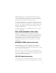
1 7 4 3 6 5 7 2 1-5
Docking Station Port Antenna Port Serial Port 1-6 RF Port Charger Port
StealthWare 3.0. Refer to page 1-21 for configuration instructions and page 2-36 for operating instructions GETTING ACQUAINTED WITH THE KEYPAD The keypad consists of the following: • three Soft keys • a Power key • four Mode Selection keys • an Enter key • eleven Alphanumeric keys • a Shift key 1 . SOFT KEYS There are three horizontally oriented soft keys located below the display.
NAVIGATOR Instantly "travel" to any mode using the NAVIGATOR. 4. ENTER KEY Press this key to terminate your entry or selection. 5. ALPHANUMERIC KEYS You use the alphanumeric keys to enter data while operating your CLI-1450. Notice that these keys have a numeral and up to three alphabetic characters labeled on them. You can only access the characters when alphanumeric entry is appropriate. In the alphanumeric entry mode, you sequence through each character and the numeral by repeatedly pressing the key.
SNAP SHOT Hold the measurement. The measurement is retained even if the cable is disconnected from the input. CLEAR Clear-out your entry and start over again. BACKLIGHT ON/OFF Quickly turn the backlight on when it is too dark to see the display. POSITIVE / NEGATIVE Enter positive and negative values (when allowed). HELP View a description of each icon found in the current soft key menu. PRINT Print a measurement screen, installation report, auto test report, or configuration report to a serial printer.
Title Bar Indicators You may see indicators appear above the title bar from time to time. This is what they represent: This indicator appears in the top right-hand corner of the screen when you press the SHIFT key. This means that the CLI-1450 interprets the next key that you press to be a secondary function. This indicator is displayed to warn you that the battery is low. When you see this, recharge the battery or change to a fresh one as soon as possible.
Lists Lists present several items for viewing and/or selecting. Notice that the currently chosen item is highlighted. You can scroll through the list using the up and down arrows. A list can be either "active" or "inactive". You can tell by looking at the border. If the border is solid, the list is active and any keys that you press are directed toward it. If the border is dim, the list is inactive and is not affected by key presses. Usually you can make a list become active by pressing the key.
THE NAVIGATOR You can easily travel to any mode using the NAVIGATOR. To access the NAVIGATOR, press the key. An icon appears on the screen for each available mode. Use the up, down, left, and right arrows to highlight the icon that represents the mode you want to use. Notice that the name of the mode appears on the lower portion of the screen beneath the status bar. To get a description of the highlighted mode, press the SHIFT + key.
To configure your CLI-1450, press the SHIFT + keys or choose icon from the NAVIGATOR. The following screen appears: the Configuration settings are divided into five categories; GLOBAL, MEASUREMENT, LEAKAGE. CHANNEL PLAN, and INGRESS. Use the up and down arrows to highlight the category you want and then press the key. Tip You can also use the left-hand and right-hand soft keys to scroll through the CONFIGURE categories and then press the middle soft key to select the highlighted category.
CONTRAST LEVEL Adjusts the contrast level of the LCD for optimum viewing. Note The contrast of the LCD is affected be variations in temperature. Your CLI-1450 will automatically optimize the contrast level based on the current temperature as measured from the built-in sensor. SHUTOFF TIME-OUT Sets the amount of inactive time allowed before your CLI-1450 turns off automatically.
turn off automatically. The indicator means that the backlight is on and will remain on continuously. If you see no indicator, the backlight is off. TIME Sets the time for the internal real-time clock. The time is set, displayed and printed in 24 hour format only (HH:MM:SS). DATE FORMAT You can specify the format in which the date is displayed and printed. Select between the following formats: MM/DD/YY DD.MM.YY YY.MM.DD DATE Sets the date for the internal real-time clock.
LINES/PAGE For text reports, you can specify the number of lines that will be printed on each page before a form feed command is sent. Enter 0 if you do not want any form feeds to be sent. BAUD RATE This is the baud rate that is used when your CLI-1450 communicates with another device through the serial port. Generally, you will want to use the highest rate supported. Be sure that the baud rate setting of your CLI-1450 matches that of the device that it is connected to.
Measurement Configuration TEMPERATURE UNITS Selects the units in which temperature measurements are displayed and printed. You can select between; °C or °F. SIGNAL LEVEL UNITS Selects the units that will be used for all signal level measurements. You can select between; dBmV, dBµV and dBm. PROBE COMPENSATION This can be used to compensate for losses associated with probe points found on certain amplifiers. You can enter a value between -99.9 and +99.9 dB.
EDIT TEST POINTS Your CLI-1450 is capable of performing tests at various locations including; SUBSCRIBER DROP, GROUND BLOCK, TAP, and USER DEFINED (or CUSTOM). Each test point has its own set of limits that you can edit. Press the key to edit the test points. A list of available test points appears. You can enable or disable each test point in the list. When a test point is disabled, you cannot use it when performing tests. Use the up or down arrow to highlight the desired test point.
You can selectively enable or disable each individual limit. When a limit is disabled, your CLI-1450 excludes it when checking limits. If the highlighted limit is disabled, you can enable it by pressing the soft key. A check mark appears in the left-hand column to indicate when a limit is enabled. If the limit is already enabled, pressing the soft key disables it. Note Analog limits are enabled by factory preset default. Digital limits are disabled by factory preset default.
Noise Floor Correction This calibration measures the noise floor of your CLI-1450. You should perform it periodically to ensure accurate measurements. IMPORTANT Before performing the Noise Floor Correction calibration, you should make sure that there is nothing connected to either the or ports (including Docking Station, DS-1) of your CLI-1450. key to initiate the calibration procedure. Your Press the CLI-1450 will guide you through the process.
Start Frequency Enter the start frequency that you want to monitor for reverse ingress. You can select from 5 to 80 MHz. Stop Frequency Enter the stop frequency that you want to monitor for reverse ingress. You can select from 5 to 80 MHz. Increment This setting affects the increment/decrement step size when you are tuning the ingress scan frequency using the left and right arrows. You can select from 25kHz to 1MHz. IMPORTANT There is a maximum of 140 measurement points.
· when the threshold is exceeded · when a tag signal is detected · when the threshold is exceeded and a tag signal is detected · disable the alarm ALARM THRESHOLD This is the leakage measurement level at which the alarm will occur. ALARM MUTE TIME-OUT When performing leakage measurements, you can mute the audible key. This setting determines the amount alarm by pressing the of time that will elapse before the alarm is reactivated.
REFERENCE DISTANCE This is the specified distance at which leakage is to be measured. For example, in the United States, the FCC requires that all measurements be referenced to 3 meters or 10 feet. If your application requires a different reference distance, enter it here. PEAK HOLD RESET PERIOD The peak hold feature momentarily holds the peak leakage measurement value. This peak value is displayed numerically and indicated on the analog meter.
the dipole antenna corresponds to theHD-1 Dipole Antenna that was shipped with your unit. If you choose to use another type of dipole antenna, you must change the antenna factor to that specified for the antenna. You can enable or disable each antenna type. When a type is disabled, you cannot use it when performing tests. Use the up or down arrow to highlight the desired antenna. If the highlighted type is disabled, you soft key.
CHANNEL PLAN CONFIGURATION What is a Channel Plan? A channel plan is a framework of cable network parameters chosen by the user for his network. The basic entities are: • Channel format (analog, digital, scrambled, etc.) • System Bandwidth • Test Limits (digital and analog) • Carriers (audio and video) Why do we need a Channel Plan? A well thought-out channel plan is necessary for the proper operation of the unit.
Using the up/down arrow keys, highlight Channel Plan and then press to bring up the Configure - Channel Plan screen. This screen lists the various ingredients/processes for building (configuring) a channel plan. Select a Channel Plan Use the up/down arrow keys to highlight SELECT CHANNEL PLAN and then press . This will bring up the Select Channel Plan screen showing the Default and other available channel plans stored in the unit. The currently active channel is denoted by an arrow tip to its left.
Select Video Signal Type Highlight VIDEO SIGNAL TYPE from the Channel Plan screen (page 1-26). Choose from NTSC, PAL and SECAM types. Press . Select Channel Sequence Highlight CHANNEL SEQUENCE from the Channel Plan screen and press to make the Edit box active. Use up/down arrow keys to select numeric or frequency. Press . NOTE NOTE: The SCAN screen always displays channels in order of frequency regardless of the CHANNEL SEQUENCE setting.
NOTE NOTE: If your system is a PAL M type, select NTSC for your channel plan. Using up or down arrow key, highlight a base channel plan from the list and then press . Press the softkey to proceed to the Build Channel Plan - STEP 3 screen Using the numeric keypad, type in a value for the Stop Frequency in the Edit box and press .Then press the right softkey. The unit will start searching for active channels and display the Build Channel Plan - STEP 4 screen.
The unit will complete the build and display the Build Channel PlanSTEP 5 screen (shown right above). Press the right softkey to return to the main Channel Plan menu (page 1-26). How to Edit the Channel Plan Why edit the Channel Plan? An accurate channel plan is essential for testing the cable system, including limits for analog and digital carriers. Editing is required to verify that the channel plan is built correctly (has the right parameters).
IMPORTANT IMPORTANT: You may find an enabled channel that is not in your channel plan. This should be disabled. A channel may be missed if the frequency is special or level too low. IMPORTANT IMPORTANT: You must enable a channel to perform measurements on it.
Type There are three channel types from which to choose: TV -the standard video and audio carriers DUAL -a video carrier with two independent audio carriers (a European format) SNGL -a single carrier Carrier (SNGL Type only -1450DIG Option) Select the format of the carrier to be measured Analog QAM (Digital) QPSK (Digital) QPR (Digital) CAP-16 (Digital) IMPORTANT: Digital signal level measurements are accurate only when performed on carriers that are in a state of continuous (non-burst) transmission.
Package You can organize channels into packages. In the edit box, you can select any package that is enabled (see the section on CHANNEL PACKAGES). When you are checking an installation, you can specify which packages the subscriber has ordered and your CLI-1450 will verify that the channels are correctly installed. Scrambled If the channel is scrambled, select YES here so that accurate measurements can be made.
How to configure a digital carrier 1. From the Configure - Edit Channel Plan screen (page 1-29), highlight the channel that you wish to configure as digital, or select an unused channel. 2. Press to bring up the Configure - Edit Channel screen. 3. Highlight TYPE, choose SNGL and press . 4. Highlight Carrier and press . Select a digital carrier (QAM, QPSK, QPR, CAP-16) and press . 5. Highlight Frequency, press . Type in a value for Center Frequency and press . 6.
Up to six channels can be selected. To select a channel, use the up or down arrow to highlight the desired channel in the list, then press the soft key. A check mark appears in the left-hand column of the list indicating that this is now a TILT channel. Also, the channel number appears in one of the six boxes above the list. Press the a second time to deselect the TILT channel. Select Channel Packages From the Configure- Channel Plan screen (page 1-26), choose CHANNEL PACKAGES.
Copy Remote Plan Once a plan has been created in one unit, it can be copied to another similar unit (Example: CLI-1450 to CLI-1450). Connect the two units with the cloning cable. Set the baud rates for the two units equal. On the host unit’s Configure - Channel Plan screen (page 1-25), select COPY REMOTE PLAN and press the OK softkey. The channel plan will be copied to the host.
MODEL CLI-1450 2 Using the CLI-1450 INTRODUCTION The best way to learn about the CLI-1450 is to use it. Section 2 discusses the individual measurements available with the CLI-1450. Each measurement mode discussion includes detailed descriptions on how to perform the measurement as well as operating controls and indicators. LEAKAGE The CLI-1450 has two sub-modes of operation that detect and measure RF leakage: the Measure mode and the Find and Fix mode.
You can read the leakage measurement numerically and on an analog meter. The units in which leakage is being measured appears directly below the meter. Note You can select the units you want to measure leakage in when you configure your CLI-1450 (see LEAKAGE UNITS in the Leakage Configuration section). The frequency being monitored appears in the upper right-hand portion of the screen.
MEASUREMENT PEAK The peak leakage value is indicated on the analog meter as a solid line. It also appears numerically as shown below: The peak value is reset periodically. You can specify how quickly you want it to reset (see PEAK HOLD RESET PERIOD in the Leakage Configuration section). Tip You can manually reset the peak value at any time by pressing the SHIFT + keys. ADJUSTING THE ALARM VOLUME An audible sound is produced when the alarm is triggered.
Note The characteristics for each type of antenna are programmable. Be sure that you have enabled all the antenna types that you want to use. soft key is only available if there is more than one enabled The type. (see EDIT ANTENNA TYPES in the Leakage Configuration section). Note The antenna selection is only useful for field strength measurements. If the measurement units you have selected result in an absolute measurement, the soft key will not be available.
COMPENSATION Compensation allows you to adjust your CLI-1450 to a calibrated leak field (see Appendix D). Press the soft key to adjust compensation. A new set of soft keys and soft keys to increment and decrewill appear. Use the ment the compensation value. You can find the compensation value in the upper right-hand portion of the screen directly below the measurement distance. Press the soft key when you have finished. Tip You can quickly clear out the compensation value by pressing the SHIFT + keys.
The Find and Fix mode assists the operator in locating the leakage source through numeric and audible alarm indicators. As your distance from the leakage point increases or decreases, the numeric indicator on the bottom-right of the screen changes to reflect the leakage level. The graph scale on the left side of the screen is controlled by the peak value, and displays the current leakage level in relation to the peak value.
PRINTING THE SCREEN You can print the entire screen at any time by pressing the SHIFT + keys. A bar graph appears indicating the status of the printout. WARNING INDICATORS If the current measurement is inaccurate due to an out-of-range condition or a hardware failure, your CLI-1450 warns you by displaying one of the following warning indicators: Over-range The leakage level is above the measurement range of the instrument. Under-range The leakage level is below the measurement range of the instrument.
Press the key to select the INSTALLATION mode or choose the icon from the NAVIGATOR. Your CLI-1450 will begin measuring all the enabled channels in the plan. A bar graph indicates the percentage of channels measured. When your CLI-1450 has finished, you can view the results and verify that all channels are within limits. SELECTING CHANNEL PACKAGES If you have configured channel packages, a list of available packages will appear. From this list, you can select the packages that the subscriber has ordered.
Subscriber Drop Ground Block Tap User Defined Note Be sure that you have enabled all of the test points that you are soft key is only available if there is more interested in using. The than one enabled test point. (see EDIT TEST POINTS). Important Only the limits that are enabled in the selected test point are checked (see EDIT TEST POINTS). INSTALLATION RESULTS SUMMARY This is the overall limit check summary for all channels in the packages that you have selected.
Note Only the limits that are enabled in the selected test point appear on this screen. If there are no enabled test points, this screen will not be available. You can however, view the CHANNEL LIST and CHANNEL MEASUREMENT screens described below. THE CHANNEL LIST Press the soft key or to sequence to the channel list screen. Tip In addition to using the and keys, you can also use the left and right arrows to sequence through the results screens.
THE PASS/FAIL INDICATOR Use the PASS/FAIL indicator located directly above the channel list to quickly determine whether the highlighted channel has passed the limits check. If the channel failed, you can identify the reason(s) for the failure by looking at the symbols that appear in this indicator.
This screen displays video and audio carrier level measurements along with the DVA for the selected channel. Use the up or down arrows to select the previous or next channel in the list. PRINTING AN INSTALLATION REPORT Press the SHIFT + keys to print a comprehensive report of the installation results. A bar graph appears indicating the status of the printout.
ADJUSTING THE REFERENCE LEVEL You can adjust the reference level setting of the analog bar meter using the up and down arrows. When you press the SHIFT + keys, your CLI-1450 automatically sets the optimum reference level for you. TUNING BY CHANNEL When you are tuned to a channel, both the video and audio carriers of the channel are measured and displayed simultaneously. The difference between the video and audio carriers (DVA) is also shown.
Use the left and right arrows to tune your CLI-1450. The frequency increments or decrements by the step size that you have specified in the Measurement configuration (see FREQUENCY TUNING STEP SIZE). You can also use the numeric entry keys to tune directly to the frequency desired. MEASUREMENT HOLD You can freeze the level measurement at any time by pressing the SHIFT + keys. The measurement is retained even if the cable is disconnected from the input port.
WARNING INDICATORS If the current measurement is inaccurate due to an out-of-range condition or hardware failure, your CLI-1450 warns you by dimming the numeric measurement value and displaying one of the following warning indicators. Over-range The signal level is above the measurement range of the instrument. Under-range The signal level is below the measurement range of the instrument. Error A hardware problem exists. If this condition persists, the unit may need repair.
MOVING THE MARKER A vertical marker appears over the currently selected channel. The channel number, type and label appear in the upper right-hand portion of the screen. The frequency and level of the video and audio carriers for the selected channel can be seen directly beneath the graph. You can use the left or right arrows to select the previous or next channel. You can also use the numeric entry keys to tune directly to the desired channel.
to zoom in and the soft key to zoom out. The magnification factor is displayed above the graph. Press the have finished. soft key when you CHECKING LIMITS You can verify that the carrier levels are within limits. First, you need to tell your CLI-1450 which test point you are at. This determines which set of limits are used. Press the soft key to access the limits submenu. A new set of soft keys appear. Press the soft key to sequence through the available test points.
When you have selected the limits submenu, the marker information below the graph is replaced by the overall limit check summary for channels currently being displayed on the graph. For each limit, the worst case actual value is displayed along with a pass/fail status. The results are updated upon the completion of each scan. Important The limit check results apply only to the channels currently being displayed on the graph — not the entire channel plan.
Up or down arrows to the left of the video level and DVA numeric measurement tell you when the limits have been exceeded. measurement too high measurement too low When an adjacent channel error occurs, one of the following indicators will appear in the lower left-hand area of the marker information area: lower adjacent channel level upper adjacent channel level both upper and lower adjacent channel levels MEASUREMENT HOLD You can freeze the scan measurement at any time by pressing the keys.
displaying one of the following warning indicators to the left of the numeric level measurement in the marker information area: Over-range The signal level is above the measurement range of the instrument. Under-range The signal level is below the measurement range of the instrument. Error A hardware problem exists. If this condition persists, the unit may need repair. TILT TILT mode simplifies the process of balancing an amplifier. TILT mode can only be accessed by choosing the icon from the NAVIGATOR.
Important You can choose which carriers appear on this screen when you configure your channel plan (see SELECT TILT CHANNELS). MOVING THE MARKER You can view up to six carriers. A vertical marker appears over the currently selected carrier. The channel number, type and label appear in the upper right-hand portion of the screen. The frequency and level of the selected carrier can be seen directly beneath the graph. You can use the left or right arrows to select the previous or next carrier.
MEASUREMENT HOLD You can freeze the tilt measurement at any time by pressing the keys. The measurement is retained even if the cable is SHIFT + disconnected from the input port. Notice that the mode icon in the upper left-hand portion of the screen flashes when the measurement is on hold. Press the SHIFT + keys again to release the hold. The measurement is not retained when another mode is selected or the CLI-1450 is shut off.
Note The channels that appear on this screen are the same ones that you selected when you configured your tilt channels. (see SELECT TILT CHANNELS). MOVING THE MARKER A vertical marker appears over the currently selected carrier. The channel number, type and label appear in the upper right-hand portion of the screen. The frequency and level of the selected carrier can be seen directly beneath the graph. You can use the left or right arrows to select the previous or next carrier.
Note Be sure that you have enabled all of the test points that you are interested in using. The soft key is only available if there is more than one enabled test point. (see EDIT TEST POINTS). When you have selected the limits submenu. the marker information below the graph is replaced by the overall limit check summary for channels currently being displayed on the graph graph. For each limit, the worst case actual value is displayed along with a pass/fail status.
PRINTING THE SCREEN You can print the entire screen at any time by pressing the SHIFT + keys. A bar graph appears indicating the status of the printout. STORING A SCAN FILE Press the SHIFT + keys to store the current scan measurement into a file. A screen will appear asking you to enter a name for the file. Once stored, you will be able to recall the file at a later time and view it on the Scan screen. You will be able to adjust the screen settings the same as when you are viewing a “live” measurement.
list. Press the soft key to select the highlighted location and continue to the next step. Tip If you are not interested in logging the information, select NONE from the list. Your CLI-1450 will present you with only the steps required to configure the test. Tip You can rename the location highlighted in the directory by pressing the SHIFT + keys. A screen will appear asking you to enter a new name. New/Edit Location This screen is where you enter the information for a new or existing location.
Measure Voltage You can log voltage measurements that you make using your multimeter. These will appear when viewing or printing the results of the Auto Test. When you have finished entering the measurements, press the soft key. Compensation Compensation is added directly to the signal level measurements. You can use this to compensate for losses associated with probe points found on certain amplifiers. The default is the Probe Compensation value specified in Configure. Enter a different value if necessary.
Temperature The ambient temperature at which the test is performed is recorded. Your CLI-1450 contains an internal temperature sensor for this purpose. If you prefer to use your own thermometer, you can manually enter the temperature here. Important For scheduled tests, the manual temperature entry is used for the first interval only. Subsequent intervals will record the temperature as measured by the internal sensor.
If you are performing a scheduled test, the time remaining until the next interval will appear upon completion of the measurements. Important To conserve battery life, your CLI-1450 will automatically shut itself off between scheduled intervals. When the auto test is complete, your CLI-1450 will display a list of Auto Test files that are available for viewing and printing. Note See the section on VIEW mode to find out how to access files from Auto Tests that you have performed.
VIEW To access measurement files that you have stored in your CLI-1450, choose the icon from the NAVIGATOR. Files are categorized into Installations, Scans (including Tilt measurements), and Auto Tests. Use the up and down arrows to select the type of file that you want to view from the main menu and then press the key. THE FILE DIRECTORY Upon selecting the file category from the VIEW main menu, you are presented with a directory of existing files.
To view a file, use the up and down arrows to highlight the name of the file that you want to view and then press either the or the soft key key. To delete the highlighted file, press the soft key. You can delete more than one file at a time by selecting multiple files using the soft key. Each press of this soft key alternately selects and deselects the file that you have highlighted. An indicator appears in the lefthand column to show that you have selected the file.
Tip You can resave an Installation file by pressing the SHIFT + This allows you to change the name of the file. keys. VIEWING SCAN FILES There are three types of scans that you can store and view — full scans, six-channel scans and tilt measurements. The type of scan depends on which screen you are in when you store the file. Once the scan is stored, you cannot change its type. Tip You can tell what type of scan you have selected in the directory without having to view it.
Note You can print the entire screen at any time by pressing the SHIFT + keys. A bar graph appears indicating the status of the printout. Note When viewing a Scan file, the date and time that the file was stored appears in the status bar and the file name appears at the top of the screen above the title bar. Tip You can resave a Scan file by pressing the SHIFT + keys. This allows you to change the name of the file and/or save any changes you have made to the screen settings.
Press the soft key to view information about the Auto Test file. This displays the information that was logged when you configured the test. The items presented depend upon the location type that you selected. Note To print a 24-hour format report, use the up and down arrows to highlight the first interval that you want included in the report and then press SHIFT + . The report will include the highlighted interval plus the following three for a total of (up to) four intervals.
The first screen that will appear is a tabular list that includes the video and audio carrier levels along with the delta V/A for each channel. Use the up and down arrows to scroll through the list. Indicators appear within the list to flag out-of-limit conditions.
Press the soft key to sequence through the available test points. The test point that you have selected is represented in the upper portion of the screen by one of the following icons: Subscriber Drop Ground Block Tap User Defined Note Be sure that you have enabled all of the test points that you are soft key is only available if there is more interested in using. The than one enabled test point. (see EDIT TEST POINTS). Only the limits that are enabled in the selected test point will be checked.
MOVING THE MARKER A vertical marker appears over the currently selected ingress frequency. The frequency and level of the ingress for the selected frequency can be seen directly beneath the graph. You can use the left or right arrows to select the previous or next frequency. ADJUSTING THE REFERENCE LEVEL The reference level setting is displayed above the graph. This is the level at the very top line. You can adjust the reference level using the up and down arrows.
THE PASS/FAIL INDICATOR Use the PASS/FAIL indicator located directly above the ingress scan to quickly determine whether the ingress scan has passed the limit check. If the scan failed, you can identify the reason(s) for the failure by looking at the ingress scan and moving the marker to identify the frequencies at which it failed. MEASUREMENT HOLD You can freeze the ingress scan measurement at any time by pressing keys.
MODEL CLI-1450 3 Reference USING THE REFERENCE SECTION This section provides additional information concerning the use of the CLI-1450. Items include; Help, Information, and Technical Support. HELP The HELP mode provides on-line user assistance by means of context-sensitive help screens. During normal operations, soft key icons appear at the bottom of the display. Each help screen describes the condition of the soft key icons at the time HELP was pressed. Press the SHIFT + key to select the HELP mode.
Example of HELP Screen Next to the icon is a brief description of the function that the soft key performs. If an icon is currently inactive "feature not available" is displayed. INFORMATION Choose the icon from the NAVIGATOR. Here you can view information concerning your CLI-1450. The type of information includes; model, frequency range, serial #, firmware version, calibration date, channel plan, memory used, and current temperature.
TECHNICAL SUPPORT Wavetek Wandel Goltermann has worked hard to make the CLI-1450 as easy-to-use as possible. However, if you have a problem using your unit you can contact WWG's Technical Support for help. You can reach WWG's Technical Support, Monday through Friday between 8 am and 5 pm EST. at (800) 622-5515 ext. 8350. For International Customers, the number to call is (317) 788-9351 788-9351. Questions may be e-mailed to Technical Support Specialists at: catvsupport@wavetek.
MODEL CLI-1450 A Appendix A: Specifications SPECIFICATIONS Frequency Range: Accuracy: Tuning Resolution: 45 to 559 MHz; 5 to 890 MHz (optional); sub band option (5 to 80 MHz) 20 ppm 25 kHz Level Measurement Range: Resolution: Accuracy1: -20 to +50 dBmV 0.1 dB +0.75 dB Flatness; +0.75 dB Linearity at 25°C (77°F) Digital Average Power: +2 .
Range: Measure Mode Accuracy: Find and Fix Mode Accuracy: CW Detection: From 0.5 µV (typical) with LT1000 Leakage Tagger activated (121 to 133.2625 MHz) Measurement: From 1.4 µV (115 to 140 MHz) 0.5 to 2,000 µV (at input connector) +1.5 dB @ 25°C (77°F) +2.25 dB @ 25°C (77°F) Tuning Tunes to video carrier frequencies in the 115 to 140 MHz range Accuracy: 20 ppm Resolution: 25 kHz General Dimensions: 4.25" (W) x 10.5" (H) x 3" (D) Weight: 1.36 kg (3 lb.) Operating Temp.
VMA-3: Magnetic mount 1/4 λ whip antenna 1019-00-0470: Cloning Cable (RS232 Interconnect cable) 1019-00-0558: Charger/Adapter universal input, 12VDC output 4010-00-0119: Charger/Adapter 120VAC to 12 VDC 4010-00-0143: MBC-4 Battery Charger 1019-00-0554: European Charger/Adapter 1019-00-0479: Field replaceable battery cartridge 1019-00-0557: Cigarette Lighter Power Adaptor MSCLI Printer: Portable serial thermal fusion printer kit 1019-00-0468: P-Stealth printer cable 1019-00-0467: Generic serial printer cable
MODEL CLI-1450 B Appendix B: Power Management and Battery Battery Pack Location and Installation The CLI-1450 battery pack (1019-00-0479) is located on the back of the unit. To remove or replace the battery pack, pull the notched tab downward, and lift the battery pack. To install the battery pack, insert the bottom of the pack into the groove and press down on the battery pack until it clicks into place. WARNING: The CLI and microStealth battery packs are NOT interchangeable.
To maximize battery life, set Auto Shutoff to 1 minute and Backlight Shutoff to "always off". These items are described in the Global Configuration section.
MODEL CLI-1450 C Appendix C: Interface Port CONNECTOR The CLI-1450 has a serial interface with RS232 drive, using a 3-pin stereo connector. The serial interface has a driver built in for RS232 serial binary data interchange. The connector is located on the bottom of the unit behind a water-resistent cover.
CABLE SPECIFICATIONS CLI-1450 TO PC (1019-00-0469) CLI-1450 TO PRINTER (STANDARD) (1019-00-0468) C-2
CLI-1450 TO CLI-1450 (1019-00-0470) CLI-1450 TO PRINTER (CITIZEN) (1019-00-0467) C-3
MODEL CLI-1450 D Appendix D: Setting Up A Calibrated Leak Field INTRODUCTION Regardless of the type of vehicle-mounted antenna used, several variables come into play that could cause a change in measured field strength. The position of the antenna on the truck will affect the ground plane and, therefore, the pattern of the antenna. There may be reflections from other devices mounted on the vehicle (ladder racks, etc.).
SETUP The frequency and level of the predictable “leak” should be given careful consideration, to avoid interfering with any off-air service or allowing an off-air service to affect the measurement. This leak should be generating a signal only during calibration and disconnected at all other times. A bandpass cable drop may be used as the leak signal, with a calibrated dipole as the source antenna. (A fixed dipole or a WWG HD-1 may be used as the source antenna.
b. Source antenna should be carefully located to isolate it from sources of reflection. c. Source antenna should be properly polarized (vertical, if vertical receiving antenna is used). 2. The following considerations should be taken into account when taking measurements using a reference leak source: a. Use a half-wave dipole when taking measurements. b. Place dipole 10 feet from the source antenna and 10 feet from ground, oriented with same polarization as source antenna.
Important Your CLI-1450 stores a separate compensation value for each antenna type. The value automatically becomes effective when you select the antenna. If you are using a calibrated leak field, be sure to make the adjustment for each type of antenna that you want to use.
MODEL CLI-1450 E Appendix E: Technical Note VMA-3 INTRODUCTION The VMA-3 Quarterwave Antenna is a field tunable antenna designed to perform leakage measurements when used with the WWG Model CLI-1450 leakage meters. The field tunable 1/4 λ antenna can be cut to any frequency in the 115-140 MHz range. INSTALLATION The VMA-3 is easy to install. To adjust the VMA-3 antenna to the desired frequency: 1. Using the cutting chart, locate the desired frequency on the horizontal axis. 2.
It is highly recommended that the element be cut long and trimmed down to the exact frequency desired. 5. Cutting the element may be easier by using the edge of a file or grinding wheel to score the rod around its circumference. Then snap it off with a pair of pliers. Always cut from the bottom of the element. 6. Insert the element all of the way into the base assembly and tighten with a 3/32" hexagon screw key. De An sired ten na Le 24 ng 23.
OPERATION For normal measurements, connect the connector on the antenna assembly directly to the antenna connection on the Model CLI-1450 leakage meter or to the DS-1 Docking Station. The antenna used in leakage detection is also referred to as a quarter-wave antenna because it is equal in length to one-quarter the measured wavelength in free space. An antenna's response (receiving or radiation) pattern is determined by its ability to receive or radiate signals better when tuned or pointed in one direction.