
User's Manual


Link-It Active Tag 10 of 15
4 TECHNICAL DESCRIPTION
4.1 PRINCIPAL OF OPERATION
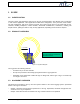
The principal of operation of the Link-It Tagging System s described in this section. A basic knowledge of the
system is essential before commencing with any installations or implementation. A basic system block dia-
gram is illustrated in Figure 4. Tags A ! N attached to assets, equipment and people are recognised and in-
terpreted by a network of Readers and Repeaters. In larger areas Repeaters are used in conjunction with
Readers to increase the area of operation. In smaller areas one reader will normally be sufficient to read all
tags in that area. Information regarding the relative tag positions is sent via cables from readers to a PC.
Large Area
Reader 1
Repeater 1
Reader 2 Reader 3
Repeater 2
Repeater 3
TagD
TagE
TagC
TagB
TagA
TagM
TagN
TagLTagJ
TagK
TagI
TagF
TagG
TagH
Small Area
Medium Size Area
Server
PC
TagO
Figure 4: Basic System Block Diagram
4.1.1 TAG TO READER/REPEATER COMMUNICATION
Tag to Reader/Repeater communication is done via a RF channel. The interface is described in paragraph
3.1.1. Tags transmit their pre-programmed ID’s at a certain time-interval. These ID’s are received and inter-
preted by the Reader/Repeater. Readers/repeaters can be configured filter data received from tags. This
means that only certain tags may be interpreted by the reader/repeater.
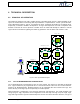
Figure 5 illustrates a configuration of two repeaters (Repeater1 and Repeater2), one reader (Reader1) and
12 tags (TagA ! TagL). Repeater2 can be configured to receive data only from tags except for TagE, TagF,
TagG and TagH. All other tags that fall within Repeater2 receive zone will be discarded. However, this type of