
User Guide

www.wavetronix.com
801.734.7200
Click 512 Vehicle Alert
QUICK START GUIDE
1
Mount the device
The Click 512 mounts over a T-bus for power and communication:
1 If the Click 512 was shipped with the T-bus connector at-
tached, remove the connector from the module.
2 Snap the connector onto the DIN rail by positioning it over
the rail with the male connector pointing to the right. Hook
one arm over the edge of the DIN rail and press down on the
other arm until it snaps into place.
3 Connect the T-bus connector to the rest of the T-bus by slid-
ing them together until you hear them snap into place.
4 Mount the Click 512 onto the DIN rail: position it properly over the T-bus connector, hook the lip over the lower edge of
the DIN rail, and use a rocking motion to snap the module into place.
If you are using a Click 200 surge protector with the Click 512, power and communication are provided to the Click 512
through the T-bus (see the Click 200 Quick Start Guide). If you don’t have a Click 200 surge protector, use the following steps
to wire power and communication into the Click 512:
1 Plug a T-bus 5-screw terminal block into the first T-bus
connector.
2 Wire DC power (10–30 V) from the power supply into the
first screw terminal on the 5-screw terminal block; wire
-DC into the second screw terminal.
3 Connect RS-485 communication (+485, -485, and GND) to
either the remaining three screw terminals on the 5-screw
terminal block or to the screw terminals in the pluggable
screw terminal block on the top of the Click 512 (see labels
for correct wiring).
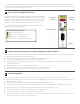
The Click 512 has three other communication ports.
˽ RJ-11 jack – Connect a jumper cable here for RS-485 communication
˽ DB-9 connector – Connect a straight-through cable here for RS-232 communication
˽ RS-232/RS-485 terminals – On top of device; usually not used
Vehicle information from the SmartSensor HD can be monitored through either digital output on the first block on the bot-
tom of the device. If you are wiring output 1 directly to a contact closure input device, wire the output O1+ and O1- (common
ground) to the input terminals. Do the same for output 2, and if you are using outputs 2–8, you will need to wire to a Click
100/112/114 contact closure card. If you need to wire to a relay, consider the Click 120.
3
Wire contact closures
2
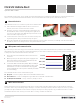
Wire power and communication
Red (+DC)
Black (-DC)
White (+485)
Blue (-485)
Drain (GND)
The Click 512 monitors lane, speed, length, and class information from a SmartSensor HD and then compares the detected
data to a set of predetermined threshold values. For more information about this product, visit wavetronix.com.