
Installation guide


SmartSensor 105 User Guide – Wavetronix LLC 9/20/07 - -
10
6. Connecting SmartSensor to Power and Communication
Devices
A typical sensor installation requires a pole-mount box containing surge protection and
connections for power and communications. SmartSensor is compatible with all standard
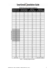
control cabinets; a table describing the SmartSensor cable’s pin-out and appropriate
connection points inside the control cabinet can be found in Appendix B of this
document.
However, to simplify the connection process, Wavetronix has developed the Click!™
product family which offers an AC to DC power supply (Click! 201/202); surge
protection for power and communications (Click! 200/204); a series of modems (Click!
300 series); wireless communications (Click! 400); and a series of contact closure
modules (Click! 100, 172, and 174). If you are connecting SmartSensor to any of the
Click! devices, please refer to the installation guide for each product for instructions; if
you are connecting SmartSensor to other manufacturer devices, please refer to the user
manuals for those products.
Connecting SmartSensor to a Surge Protection Device
It is strongly recommended that the SmartSensor be connected to a surge protection
device. The Wavetronix Click! 200 and equivalent devices are designed to prevent
electrical surges from damaging the sensor.
If using Click! 200 devices, ALL Click! 200 devices must be mounted on a DIN rail that
is connected to earth ground either through an earth grounded chassis or a 16 AWG or
larger grounding wire attached to a 7’ grounding rod.
If you choose not to use surge protection in your installation, please contact Wavetronix
Technical Support for assistance.
Short Cable Run (40 feet or less)
A short cable run usually indicates any installation with a SmartSensor cable 40 feet or
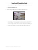
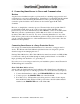
less. Follow the steps below to add surge protection on a short cable run (see Figure 5):
1. Connect the SmartSensor cable to the UNPROTECTED side of the Click! 200.
2. Connect power to the PROTECTED side of the Click! 200.
3. If a Click! 172 or 174 Input file card is being used for contact closure outputs,
then the RS-485 cable and the 24 VDC power in the controller cabinet must be
attached to the PROTECTED side of the Click! 200.