
Installation guide


SmartSensor 105 User Guide – Wavetronix LLC 9/20/07 - -
25
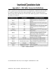
Appendix B – Cable Connector Definitions
The SmartSensor cable is comprised of three groups of wires. Each group contains color-
coded wires accompanied by a drain wire and surrounded by a shield. The following
table details the pin out of the cable and the appropriate connection inside the cabinet for
each wire:
Table 3 – SmartSensor Cable and Cabinet Connection
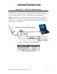
See Figure 16 for a diagram of the previously used SmartSensor cable’s 25-pin socket
assignment. The codes listed in the diagram are to be used to solder wires into the back
of the plug where the letters represent the individual solder cups.