
User guide


CHAPTER 5 COMMUNICATION 55
be set to default values.
Note
It is recommended that you label the service end of each SmartSensor Matrix cable
when the cable is pulled so that the approach the sensor is monitoring can be
documented. You may need to power down all sensors except for the one you are
configuring in order to determine which approach it is monitoring.
If you have problems connecting:
1 Make sure that all power and communication wiring is correct.
2 Check the port settings (Port ID).
Connection failure can occur for various reasons; if a failure occurs repeatedly, call Wavetro-
nix Technical Support at 801-734-7200 for assistance.
Once you have selected a sensor from the device list, you can click again on that
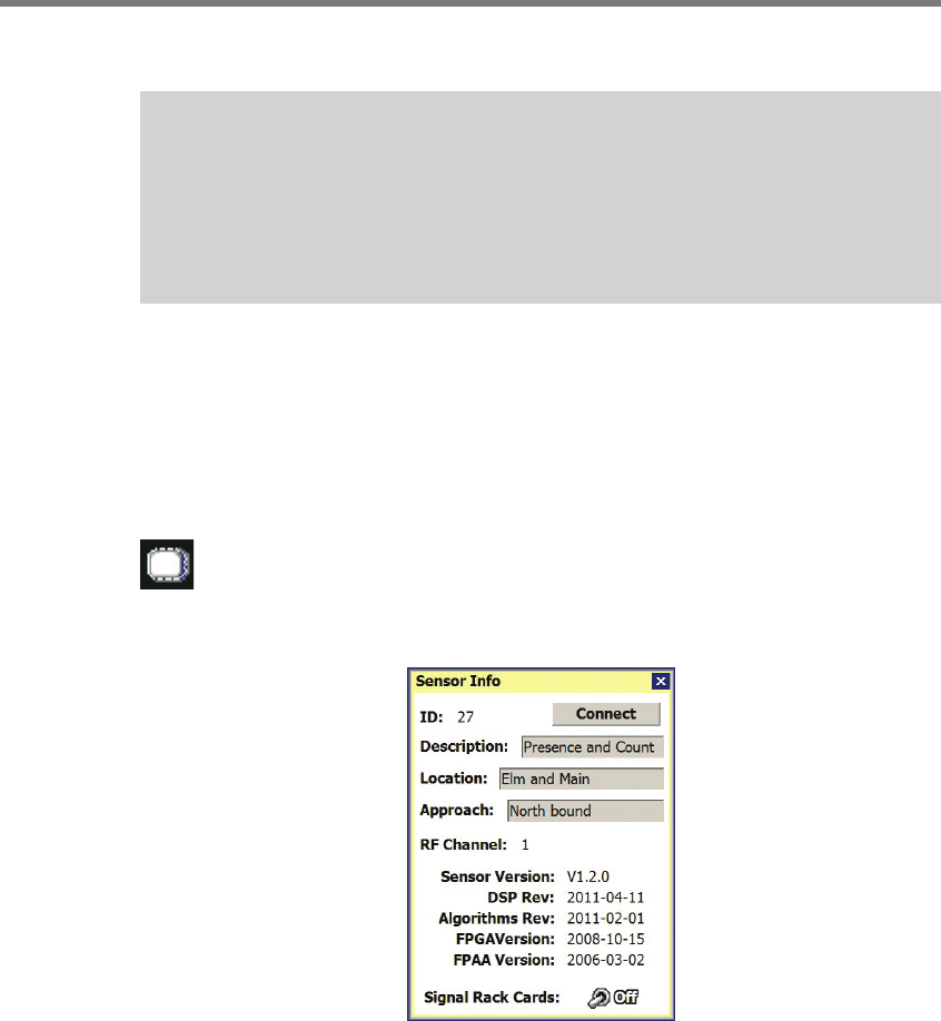
row to bring up a Sensor Info pop-up (see Figure 5.5). To bring up the Sensor Info
pop-up, you can also click on the sensor icon that appears in the upper right corner
of the screen (see Figure 5.4). e information in the Sensor Info screen cannot be edited.
Figure 5.5 – Sensor Info Screen
e Sensor Info screen lists the following sensor settings and version information:
Sensor ID – e last seven digits of the sensor serial number. is eld is not editable.
Description – Used to describe the application (e.g. stop bar detection); can also be
used for GPS coordinates. is eld is not editable from this screen.
Location – Used to describe the intersection where the sensor is located. is eld is
not editable from this screen.
Approach – Used to indicate which approach of the intersection the sensor monitors.