
User's Manual

6
INTRODUCTION o SMARTSENSOR USER GUIDE
SmartSensor 105 Package
A typical sensor package contains the following items:
10.525 GHz SmartSensor Radar Trac Sensor
SmartSensor mounting kit
SmartSensor cable
SmartSensor Manager software
SmartSensor User Guide
Caution
Check the packing slip for actual contents. If any of these items are missing,
note the serial number located on the back of the sensor and contact your
distributor.
Additional products may be purchased through your distributor. The following
optional items are not included unless specically ordered (check packing list for
actual inventory):
Click! 172/174™ contact closure adapter
Click! 200™ surge protector
Click! 201/202™ AC to DC converter
Click! 210™ circuit breaker and switch
Click! 230™ AC surge module
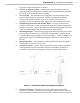
Selecting a Mounting Location
Consider the following guidelines when selecting a mounting location:
Lane Coverage –
Sensor mounting locations should be selected so that all
monitored lanes are within 10 to 200 ft. (3 to 61 m) and run parallel with
each other. If more than eight lanes need to be simultaneously monitored,
consider using multiple sensors or the SmartSensor HD, which can monitor
up to 10 lanes simultaneously.
Parallel Lanes –
When the sensor is used to collect both mainline and
ramp data, the pole position should be selected so that the on and o ramp
lanes run parallel with the mainline. If lanes are not parallel, installation
of multiple SmartSensor units should be considered to achieve the sensor’s
±2° side-to-side angle requirement.
Sensors on the Same Pole –
When multiple sensors are mounted on the
same pole, they will not be subject to interference if they are congured to
operating using dierent RF channels and are separated vertically by a few
feet. The higher sensor would typically be used for the lanes further from