
User's Manual

7
INTRODUCTION o SMARTSENSOR USER GUIDE
the pole in order to minimize occlusion.
Sensors on Opposing Poles –
SmartSensor units facing each other on
opposing poles should operate on dierent RF channels and be separated
by a 40-ft. (12.2-m) lateral oset, if possible.
Line of Sight –
The SmartSensor is designed to work accurately in the
presence of barriers, but in general if there is an alternate mounting
location that would avoid any type of structural occlusion, this is
preferred. Avoid occlusion by trees, signs, and other roadside structures.
Neighboring Structures and Parallel Walls –
It is also preferred that
sensor locations have a 30-ft. (9.1-m) lateral separation from overhead sign
bridges, overpasses, tunnels, parallel walls and parallel-parked vehicles in
order to avoid multiple reection paths from a single vehicle.
Mounting Height –
The mounting height should be based upon the oset
from the lanes of interest. For each oset, the minimum, maximum and
recommended range of heights is shown in Table 1.1, found in chapter 1. In
general, the range of recommended heights is between 9 and 50 ft. (2.7 to
15.2 m).
Mounting Oset –
The minimum recommended oset from the edge of
the rst lane of interest is 10 ft. (3 m).
Arterial Locations –
Sensor sites on arterials or other roadway segments
with regulated stop lines should be selected at mid-block positions to
increase accuracy by increasing line of sight to stop-and-go vehicles.
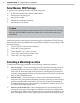
Portable (left) and Permanent (right) Sensor Stations Figure I.1 –
Freeway Locations –
SmartSensor is often used at permanent ATR
stations. The number of stations along a single roadway and the distance
between stations should be selected to achieve adequate levels of statistical