
User's Manual

56
CHAPTer 5 o SENSOR SETTINGS
lost. However, if there is only one sensor connected to the data bus, there
should be no collisions in data push mode.
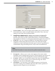
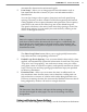
Before you change to Data Push mode, select the desired port and data
type from the drop-down lists provided. You can set the sensor up to push
data over more than one port. You can also set it up to push multiple types
of data over the same port. To change to Data Push mode, click on the
Enabled checkbox next to each one of the four ports you wish to enable.
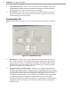
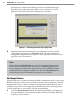
Data Collection Tab
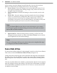
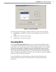
The Data Collection tab allows you to edit the following seings (see Figure 5.7):
Data Collection TabFigure 5.4 –
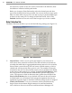
Interval Data –
Allows you to specify the length of your intervals as
well as how those intervals are stored. The interval refers to the time (in
seconds) that trac data is aggregated (minimum interval is ve seconds).
Interval data is stored directly into the sensor’s SRAM memory, which is
volatile and will not persist after a power cycle. The number of intervals
is limited to 246. You can also tell the sensor to move the data from SRAM
to the sensor’s ash memory by clicking the Store in Flash Memory check
box. This protects the data because ash memory persists after power
cycles. The capacity in ash is about ten times greater than SRAM. If the
Store in Flash Memory box is not checked, the interval data will remain
in SRAM until it is overwrien. Flash storage management features are
explained in greater depth in the Data Collection Setup section of chapter 7.
Vehicle Classication –
Lets you customize vehicle classications by
length. Enter the maximum length amounts for small and medium
class vehicles in the active text boxes and SmartSensor Manager will