
User's Manual

91
CHAPTer 9 o CONTACT CLOSURE COMMUNICATIONS
Tip
In many cases, the trac data detected by SmartSensor is valuable to both
operations and planning departments. However, when legacy systems are
used, often there is no mechanism to directly share the data. Even with the
limitations of legacy systems, contact closures can sometimes provide a
way for operations and planning to both get what they need from a single
sensor. For example, the operations department can collect trac data into
a trac controller via a Click! 172/174 over one of the SmartSensor’s two
ports. Then the planning department can use the second port to send data
to an automatic trac data recorder via a Click! 100.
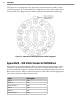
Click! 500 –
The Click! 500 is a user-programmable contact closure
platform for virtually any application. For example, the Click! 500 can be
programmed to activate a contact closure output when vehicles over a
specied speed and length are detected. To accelerate development, the
Click! 500 will provide developers with SmartSensor communication
drivers.
For a full description of each module refer to the Click! quick-start guides, user
manuals and bid specications. Or contact your authorized Wavetronix dealer or
Wavetronix Technical Services for more information.
Programming Sensors for Use with Contact Closures
Click! 100 –
The Click! 100 supports baud rates from 9600 to 57600 bps.
When using a Click! 100, make sure your SmartSensor is set to operate at a
baud rate in this range.
Click! 101 –
The Click! 101 modules support baud rates from 9600 to 115200
bps. The Click! 101 identies each sensor by its sensor ID. Before you
congure the Click! 101, you can retrieve the sensor ID using SmartSensor
Manager over communication link.
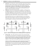
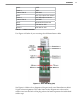
Click! 172/174 –
The Click! 172/174 modules support baud rates from 9600
to 57600 bps. When using a Click! 172/174 device, make sure SmartSensor
is set to operate at a baud rate in this range. To select which SmartSensor
lanes are mapped to the Click! 172/174 outputs, the lane names of the
SmartSensor need to be set up correctly using SmartSensor Manager. The
rst character of the lane name should take on the value 0 to 9. The second
character can take on a value R or L to represent the direction trac is
owing. For example, lane names could be 1R (right to left) or 1L (left to
right).