
User's Manual

In the Appendix
A – Cable Connector Denitions
B – Old Cable Connector Denitions
C – Cable Lengths
D – Direct Serial Connections
Appendix
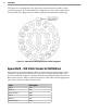
Appendix A – Cable Connector Denitions
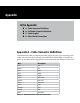
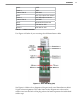
The SmartSensor cable is composed of three groups of wires, each containing color-
coded wires and a drain wire and surrounded by a shield. Table A.1 details the
pinout of the cable and the appropriate connection inside the cabinet for each wire:
Wire Description
Red +DC
Black -DC
Drain GND
Blue -485
White +485
Drain 485 GND
Yellow 232 (TD)
Violet 232 (RD)
Drain GND
Orange RTS
Brown CTS
Gray 232 GND
SmartSensor Cable and Cabinet ConnectionTable A.1 –