
User's Manual

94 APPeNdiX
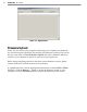
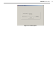
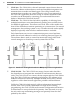
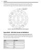
See Figure A.1 for a diagram of the previously used SmartSensor cable’s 25-pin
socket assignment. The codes listed in the diagram are to be used to solder wires
into the back of the plug where the leers represent the individual solder cups.
SmartSensor 105 Plug Connector Socket AssignmentFigure A.1 –
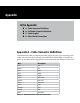
Appendix B – Old Cable Connector Denitions
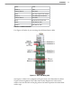
The previously used SmartSensor cable is composed of six twisted pairs of wire.
Each pair is composed of a black and a red wire, accompanied by a drain wire
and surrounded by a shield. A numeric label (1 through 6) identies each pair of
black and red wires. Table A.2 details the pinout of the cable and the appropriate
connection inside the cabinet for each wire:
Cable Description
Red 1 +DC
Black 1 -DC
Drain of Pair 1 GND
Red 2 +DC
Black 2 -DC
Drain of Pair 2 GND