
User's Manual
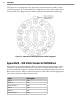

95APPeNdiX
Red 3 +485
Black 3 -485
Drain of Pair 3 485 GND
Red 4 232 (TD) output from sensor
Black 4 232 (RD) input to sensor
Drain of Pair 4 232 GND
Pair 5 Reserved for future use
Red 6 CTS ow for 232
Black 6 RTS ow for 232
Cabinet ConnectionTable A.2 –
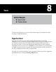
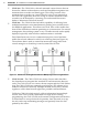
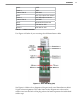
Use Figure A.2 below if you are using the old SmartSensor cable:
Click! 200 Wiring (Old)Figure A.2 –
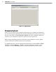
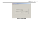
See Figure A.3 below for a diagram of the previously used SmartSensor cable’s
25-pin socket assignment. The codes listed in the diagram are to be used to
solder wires into the back of the plug where the leers represent the individual
solder cups.