TM Wavetronix LLC www.SmartSensor.us SmartSensor HDTM SS 126 User’s Manual Version 1.0 March 13, 2013 5314 N. 250 W.
Wavetronix LLC TM Wavetronix Contact Information .................................................................................................... 2 Copyright / Trademarks .................................................................................................................. 2 Product Notifications ...................................................................................................................... 3 Introduction ...............................................................
Wavetronix LLC TM Wavetronix Contact Information 380 S. Technology Ct. Lindon, Utah 840424 USA Voice: (801) 764-0277 Fax: (801) 764-0208 Web: www.smartsensor.us E-mail: sales@smartsensor.us Or support@smartsensor.us Copyright / Trademarks © Copyright 2002 Wavetronix LLC, All rights reserved. SmartSensor, the SmartSensor logo and LaneSmart are trademarks of Wavetronix LLC. SeaLINK is a trademark of Sealevel Systems Inc.
Wavetronix LLC TM Product Notifications FCC Part 15 Compliance This equipment complies with Part 15 of the FCC (Federal Communications Commission) rules. Any changes or modifications not expressly approved by the manufacturer could void the user’s authority to operate the equipment. Note: This equipment has been tested and found to comply with the limits for a Class A digital device, pursuant to part 15 of the FCC Rules.
Wavetronix LLC TM and safety procedures as they relate to specific locations and installations. Symbol Legend The lightning bolt within an equilateral triangle symbol is intended to alert the user to the risk of electric shock. The exclamation point within an equilateral triangle is intended to alert the user to the presence of important installation, operating, and maintenance instructions.
Wavetronix LLC TM Introduction The Wavetronix SmartSensor HD traffic sensor utilizes the latest technology to collect and deliver traffic statistics. Capable of measuring traffic volume, average speed, individual vehicle speed, lane occupancy and presence, the SmartSensor HD collects information through the use of a 24.125 GHz (K band) operating radio frequency.
Wavetronix LLC TM Unpacking A typical sensor packages contains the following items: SmartSensor HD SS-126 detector Stainless steel mounting plate Mounting fasteners Sensor mount bracket Sensor cable User’s Manual CD and/or diskette with software If any of these items are missing, note the serial number located on the side of the sensor and contact the Wavetronix support.
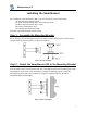
Wavetronix LLC TM Installing the SmartSensor The installation of the SmartSensor HD is a process that involves five simple steps: (1) Assemble the mounting bracket. (2) Attach the SmartSensor HD to the mounting bracket. (3) Mount the SmartSensor HD to a pole. (4) Connect SmartSensor cable. (5) Configure the SmartSensor HD. Each step is described in detail in this section.
Wavetronix LLC TM Step 3 - Mount SmartSensor HD on a Pole Firmly secure the SmartSensor to a pole or fixed location at a height between 4 and 10 m from the desired monitoring surface. Firmly secure the mounting bracket on a vertical or horizontal pole using the ½ inch band straps included in shipment. The bracket is adjustable and has 70° of tilt adjustability. Aim the front of sensor at the center of the detection area.
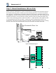
Wavetronix LLC TM Step 4 – Connect SmartSensor Cable The sensor connector as shown in Figure 5 a. is keyed such that it can only fit one way. Attach it to the coupling at the base of the sensor. The cable should be strapped to the pole or run through conduit to reduce the strain on the cable. Figure 5 a. Sensor Connector b. Service End The service end of the cable (Figure 5 b.) has a +DC and GND for a power supply of 12 to 24 VDC.
Wavetronix LLC TM Step 5 – Configure the SmartSensor HD To confirm the configuration of lanes (detection zones) on the SmartSensor HD connect to the SmartSensor HD through a serial, Internet, or modem connection. To do this you must first install the SmartSensor Manager CE on a pocket PC or laptop; second, connect the SmartSensor HD to your pocket PC or laptop; third, use the Lane Configuration utility under Lane Setup in SmartSensor Manager CE to confirm and save the configuration of lanes in the sensor.
Wavetronix LLC TM Step 5.2 - Connecting Your Computer to the SmartSensor HD There are several ways to connect your computer to the SmartSensor HD as listed below. Step 5.2.1 – Physically Connecting the SmartSensor HD to your Computer Serial Cable – there are two serial options available for connecting to the SmartSensor HD: 1. RS-232 using a 9-pin null modem serial cable connected to the standard RS-232 serial port on your PC. This configuration is shown in Figure 7 below.
Wavetronix LLC TM could be a regular POTS analog modem or a wireless modem (GSM, etc.) if service is available in your area. Internet – the SmartSensor HD can be connected to the Internet allowing access to the sensor from anywhere with Internet access. There are two ways to connect the Smart Sensor to the Internet: 1. CDMA modem – Code Division Multiple Access (CDMA) is a wireless Internet service available in most metropolitan areas in the United States and coverage continues to expand.
Wavetronix LLC TM This can easily be done by highlighting the most significant digit (10,000) and scrolling it up past 60,000. Next click connect and you should be connected. Figure 10 Internet Connection If you chose “Internet” under Connection, in the communication dialog window (Figure 10) you must then enter the Internet address (IP address & TCP port number) of the sensor of interest. The first box is used for the IP address, which consists of four numbers ranging from 0-255 separated by dots (‘.’).
Wavetronix LLC TM Step 5.2.3 - Using SmartSensor Manager CE’s Lane Configuration Utility After a connection is made to the SmartSensor the home page as shown in Figure 11 appears. To configure lanes click on Lane Setup. Figure 11 The lane setup options window then appears as shown in Figure 12. To start the lane configuration process the Lane Configuration button.
Wavetronix LLC TM Figure 13 Automatic Configuration That completes the normal installation and configuration process.
Wavetronix LLC TM Additional Features of SmartSensor Manager CE The SmartSensor Manager is designed to quickly confirm or adjust the configuration of the SmartSensor, tools to verify the performance of the SmartSensor and upgrade the SmartSensor. Manual Configuration The newly activated buttons remain pressed when you click them to enable the drawing function of the button you press. To change the configuration, click the appropriate button and move your cursor over the window showing roads and vehicles.
Wavetronix LLC TM Data Logs Firmware Upload Appendix SmartSensor Specifications Operating Frequency: Detection Zones: Detection Range: Measured Quantities: Communications: Power: Weight: Physical Dimensions: Zone Resolution: Ambient Operating Temp: Humidity: Shock: Transmitted Power at 3m: 24.125 GHz (K-band) Up to 10 traffic lanes simultaneously 250 ft Speed, occupancy, volume, presence, classification RS-485 or RS-232 connection 8 watts @ 9-30 VDC 5 lbs. 27 cm. H x 33.5 cm W x 8.
Wavetronix LLC TM Cable Connector Definitions RS-232 Communication Port The RS-232 Communication Port is configured in a 9-pin “D” male connector with the following pin out: RS-232 Pin Out 1: N/C 2: Data from Modem 3: Data to Modem 4: N/C 5: GND 6. N/C 7. N/C 8. N/C 9.