
User's Manual

TMTM
9
Wavetronix LLC
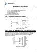
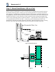
Step 4 – Connect SmartSensor Cable
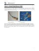
The sensor connector as shown in Figure 5 a. is keyed such that it can only fit one way. Attach it
to the coupling at the base of the sensor. The cable should be strapped to the pole or run through
conduit to reduce the strain on the cable.
Figure 5
a. Sensor Connector b. Service End
The service end of the cable (Figure 5 b.) has a +DC and GND for a power supply of 12 to 24
VDC. Up to three communication ports (either RS-232 or RS-485) are available to connect the
SmartSensor to a modem or other communication device. Typically one RS-485 port is available
plus one or two RS-232 ports. Figure 5 shows 2 communication ports. Refer to the appendix for
pin assignments.