WBS-2400 & WBS-5800 Outdoor Wi-Fi Sector Base Station Installation Guide Rev.
Note: To better reflect the value of Wavion products we are changing the name of our product family from Access Points (AP) to Wireless Base Stations (WBS), consequently the existing WS410 product name will be changed to Wavion WBS-2400.
Warning: Changes or modifications to this unit not expressly approved by the party responsible for compliance could void the user’s authority to operate the equipment. Note: This device complies with part 15 of the FCC Rules. Operation is subject to the following two conditions: (1) This device may not cause harmful interference, and (2) this device must accept any interference received, including interference that may cause undesired operation.
Contents About This Guide ........................................................................ 5 Preface .................................................................................................... 5 Conventions ............................................................................................. 5 Contacting Technical Support .................................................................... 6 2 Introduction .............................................................................
Chapter 1 About This Guide Preface This guide details the Wavion WBS-2400/5800 Sector installation procedures. The intended audience of this document is trained technical professionals. Conventions The exclamation point within a triangle is intended to alert the user to the presence of important operating and maintenance (servicing) instructions in the literature accompanying the product.
About This Guide Contacting Technical Support For technical support, contact Wavion using these methods: 6 Address: Wavion Technical Support Wavion 6 Hayetzira Street, PO BOX 580 Yoqneam Illit, 20692 Israel Telephone: +972-4-9097300 Fax: +972-4-9097322 Email: support@wavionnetworks.com Web: www.wavionnetworks.
Introduction Chapter 2 Introduction WBS-2400/5800 Sector a high capacity, IP services oriented Broadband Wireless access system. WBS-2400/5800 Sector is a new category of Broadband Wireless Base Station designed from the ground up for metro-Wi-Fi deployments. The system employs wireless packet switched data technology to support high-speed IP services including fast Internet and Virtual Private Networks.
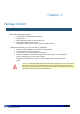
Chapter 3 Package Content Check that the package contains: • POE injector unit with wall mounting kit • Outdoor Unit • Pole mounting bracket for the outdoor unit • Allen head wrench with 4 screws • Waterproof sealing tape for IP67 (band to sealing rubber) Additional Equipment and Tools required for Installation • Ethernet cable (straight for connecting to a hub/switch) • Crimping tool for RJ-45 connectors. • Ground cable with an appropriate termination.
Package Content • • Addition tools and materials, including appropriate means (e.g. a pole) for installing the outdoor equipment. 1/4-inch flat blade screwdriver WARNING: ONLY experienced installation professionals who are familiar with local building and safety codes and, wherever applicable, are licensed by the appropriate government regulatory authorities should install outdoor units and antennas.
Chapter 4 Installing the Wavion WBS-2400/5800 Sector Base Station This guide explains how to safely install the Wavion WBS-2400/5800 Sector Base Station.
Important Safety Instructions WARNING: It is illegal to modify the construction of this product. Modifying the operating frequency or enhancing the transmit output power through the use of external amplifiers or other equipment is specifically disallowed by the "Telecommunications Act." WARNING: This device is for outdoor or indoor use with conditions that no harmful interference to authorized radio stations results from the operation of this device.
Caution: There are no user-serviceable parts inside. All service must be performed by qualified personnel. Caution Only UL listed parts and components will be used for installation. Use UL listed devices having an environmental rating equal to or better than the enclosure rating to close all unfilled openings. Caution To maintain Overvoltage (Installation) Category II, install a suitable surge suppressor device in the branch circuit to limit expected transients to Overvoltage Category II values.
Choosing a Location To ensure the optimal performance select the locations for the equipment using the following guidelines: The antenna (integrated on the front panel of the outdoor unit) should provide a direct, or near line of sight, with the sector location that need to be covered. The antenna should be aligned to face the CPEs that aim to be in service, higher the placement of the antenna, the better the achievable link quality (but not in all cases).
Mounting Strategies Consider the available mounting structures and antenna clearance when choosing a mounting location. Wavion outdoor unit WBS-2400/5800 Sector should be mounted on horizontal pole only the antennas pointing vertically and clear of obstruction. It is recommended to attach ground and data cables to the WBS-2400/5800 Sector prior to mounting. Before mounting the WBS-2400/5800 Sector, read the wiring instructions in Grounding the Wavion WBS-2400/5800 and Connecting Power and Data.
Figure 4.2 Using Special Hose Clamps & Screwing the Clamps Mounting on a Pole/Streetlight WBS-2400/5800 Sector can be mounted on a pole, tower, or streetlight. It is recommended to mount the WBS-2400/5800 Sector on aluminum or galvanized steel structures. Note Before mounting the WBS-2400/5800, read the wiring instructions in Grounding the Wavion WBS-2400/5800 and Connecting a Data Port chapter.
To mount the Wavion WBS-2400/5800 on a metal/wood/streetlight pole: 1. Choose a mounting location. You can attach the WBS-2400/5800 Sector outdoor unit to any pole or pipe with diameter of 3-10 inches. Wooden poles of larger diameter require different types of clamps (any streetlight arm with diameter of 3 to 10 inches will fit for this installation). 2. Slip the bands of the hose clamps through the slots of the pole bracket 3. Use the hose clamps to fasten the pole bracket to the pole. 4.
Note: The WBS-2400/5800 unit must be parallel to the ground. The unit can be rotated to obtain the correct position. Note Installations on large wooden poles require band clamps such as those supplied by Panduit, www.panduit.com. Such a product is listed as "Metal, Locking Tie Extra Heavy Duty 304 Stainless Steel".
To ground the Wavion WBS-2400/5800: The Grounding screw is located on the side panel of the outdoor unit. To connect the grounding cable: 1. Connect one end of a grounding cable to the grounding terminal and tighten the grounding screw firmly. Do the following steps: a. Remove the nut and star washers from the grounding screw. b. Attach one star washer to the grounding screw. c. Attach #10 AWG bare copper wires with an M6 terminal ring to the grounding screw. d.
Figure 4.6 Grounding indoor injector by Network Protection Unit Figure 4.
Connecting Power and DATA The following describes how to apply power and data to the WBS-2400/5800X Caution: You must always install an external grounding wire. Perform a simple continuity check between the WBS-2400/5800and the ground termination point to confirm. You must also ground the outdoor data protection device to a ground rod or a bonded pipe. Make sure you have completed grounding before you connect power to the WBS-2400/5800X. The Wavion WBS-2400/5800 is equipped with two RJ45 connectors.
WARNING: The shields of the Cat5 cable must be properly terminated and bonded to the unit and to the protective earth (PE) at the building entrance. This provides protection against the risk of fire, electrical hazard and ensures the reliable operation of this equipment. Note: National Electrical Codes (NEC) Article 800 requires the use of an Agency Listed (UL/CSA) Building Entrance Protector for all power and communications cables entering a building.
Figure 4.9 Sealing rubber 7.
Figure 4.10 Sealing rubber 8. Tighten the band on sealing rubber for better sealing or using weatherproof Stripe. Note: Use high quality sealing material such as Scotch® 130C Linerless Rubber (attached to the product) Splicing Tape from 3M to ensure IP-67 compliant protection against dust and water. Figure 4.11 Weatherproof Stripe sealing 9. Connect the data cable from the network to "Ethernet" port of POE injector. 10. Connect POE injector to AC power source to power WBS-2400/5800 unit.
POE port RJ45 Pin Descriptions Pin T/R Signal Color Description 1 T TXD+ Orange-White TX Data 10/100BaseT 2 R TXD- Orange TX Data 10/100BaseT 3 T RXD+ Green-White RX Data 10/100BaseT 4 R PoE+ Blue Power input, 55 VDC (+) 5 T PoE+ Blue-White Power input, 55 VDC (+) 6 R RXD- Green RX Data 10/100BaseT 7 T PoE- Brown-White Power input, 55 VDC (-) 8 R PoE- Brown Power input, 55 VDC (-) Safety Information for the Wavion WBS-2400/5800 The Federal Communications Commissi
Service Instructions The Wavion WBS-2400/5800 contains no user serviceable parts inside.
Chapter 5 Product Specification WBS-2400 Sector The tables in this chapter contain specifications for the Wavion WBS-2400. Wireless Specifications compliant Frequency band IEEE 802.11b/g 2.4 - 2.483 GHz • 802.11b: DSSS (DBPSK, DQPSK, CCK) • 802.11g: OFDM (64QAM, 16QAM, QPSK, BPSK) Modulation TX Power Maximum 802.11b and 802.11g Beamformer Directed Power EIRP + Beamfroming gain: 42.5dBm EIRP Calculations Antenna Gain - 10.5 dBi Total EIRP - 34.5 dBm RX Sensitivity* 802.11b and 802.
dBm @ Mbps -92 dBm @ 36 Mbps -88 dBm @ 48 Mbps -86 dBm @ 54 Mbps Security Specifications Packet filtering via layer 2 & 3 WEP (64 bit or 128 bit) WPA: Encryption: WEP or TKIP Authentication: Pre-Shared Key or 802.
Physical Specifications Network Interfaces • Auto-sensing 10/100 Ethernet • Input from Wavion Injector Power Input • Power from a Wavion POE Injector. Indicator Lights • Ethernet port LED Link/Act indicator • System Status LED indicator • RF channel status indicator Physical Dimensions • Height: 9 cm • Length: 39 cm • Width: 36 cm • Weight: 4.6 Kg without mounting brackets Power Specifications • Power Input • 55VDC, supplied over Ethernet from Wavion injector.
Environmental Specifications Operating Temperature Range -40°C to +55°C (without Sun Shield) -40°C to +60°C (with Sun Shield) Storage Temperature Range -45°C to +85°C Weather Rating IP67 Wind Survivability 165 mph Salt and Fog Rust Resistance MIL-STD-810F 509.4 Shock and Vibration ESTI 300-192-4 spec T41.E Transportation ISTA2A Approvals RF Safety FCC CFR 47 part 15, Sub Part C ETSI 300 328 V1.7.
Chapter 6 Antenna 2.4GHz Specifications and Patterns The chapter describes antenna specifications and patterns for the antennas supplied with the Wavion WBS-2400. SF-245W 2.4GHz Sector Antenna 2.
Antenna Electrical Specifications Number of antennas 3 Frequency Range 2.4 - 2.4835 GHz Peak Gain 2.4-2.4835 GHz 10.5 dBi (min) 0 dBi (max) design goal at all directions -8 dBi (max) design goal at all directions VSWR 1.5 :1 (max) R.L.
Antenna ENVIRONMENTAL TEST Water Tightness Internal pressure Solar Radiation Flammability Salt Spray Ice And Snow Wind Speed Survival Operation STANDARD DURATION TEMPERATURE NOTES IEC 529 - - ASTM G53 UL 94 IEC 68-2-11 Ka 1000 h 500 h - - - - 25mm Radial - - - 266 Km/h 160 Km/h IP67*** TBD **** Class HB - Regulatory Compliance RoHS , CE 0682 Low Temperature IEC 68-2-1 72 h -45°C - High Temperature IEC 68-2-2 72 h +90°C - Temp.
Chapter 7 Product Specification WBS-5800 The tables in this chapter contain specifications for the Wavion WBS-5800. Wireless Specifications compliant IEEE 802.11b/g Frequency band 5.725–5.850 GHz Modulation 802.11a: OFDM (64QAM, 16QAM, QPSK, BPSK) TX Power Maximum Max. power per antenna: 19dBm (FCC version Maximum transmit power will vary by channel and data rate) Beamformer Directed Power EIRP + Beamfroming gain: 43dBm EIRP Calculations Antenna Gain – 12.5 dBi Total EIRP - 35.
Management Specifications Web based configuration and management too SNMPv2 with standard and Wavion MIB support Configuration save and restore Network and client statistics Security Specifications Packet filtering via layer 2 & 3 WEP (64 bit or 128 bit) WPA: Encryption: WEP or TKIP Authentication: Pre-Shared Key or 802.1x with RADIUS Server (EAP-TLS, PEAP, EAP-TTLS) VPN pass-through and tagging HTTPS for web-based management tools Networking and QoS Specifications Full 802.
Physical Specifications Network Interfaces • Auto-sensing 10/100 Ethernet • Input from Wavion Injector Power Input • Power from a Wavion POE Injector. Indicator Lights • Ethernet port LED Link/Act indicator • System Status LED indicator • RF channel status indicator Physical Dimensions • Height: 9 cm • Length: 39 cm • Width: 36 cm • Weight: 4.6 Kg without mounting brackets Power Specifications • Power Input • 55VDC, supplied over Ethernet from Wavion injector.
Approvals FCC CFR 47 part 15, Sub Part C RF Safety EMC 36 Wavion Networks TUVus EN 60950-1:2001+A11:2004 IEC 60950-1:2001 First Edition Information Technology equipment – Safety – Part 1 FCC CFR 47 Part 15, Sub Part B, Class B (USA)
Water Tightness IEC 529 - - IP67*** Antenna Electrical Specifications Number of antennas Frequency Range Peak Gain 5.7 - 5.9 GHz 3 5.7 - 5.9 GHz 12.5 dBi VSWR 1.
ENVIRONMENTAL TEST Internal pressure Solar Radiation Flammability Salt Spray Ice And Snow Wind Speed Survival Operation STANDARD DURATION TEMPERATURE NOTES TBD **** Class HB - ASTM G53 UL 94 IEC 68-2-11 Ka 1000 h 500 h - - - - 25mm Radial - - - 266 Km/h 160 Km/h Regulatory Compliance RoHS , CE 0682 Low Temperature IEC 68-2-1 72 h -45°C - High Temperature IEC 68-2-2 72 h +90°C - Temp.
Chapter 8 Antenna 5.8GHz Specifications and Patterns The chapter describes antenna specifications and patterns for the antennas supplied with the Wavion WBS-5800. MT-463009CV 5.
MT-463009CV 5.
Chapter 9 Installation Accessories This chapter describes the accessories available for the WBS-2400 and ordering information.
Ethernet Cables Description Manufacturer Part Number Distributor Contact Information Outdoor CAT5e double jacket 4-pair data cable Teldor 8393204101 G.Bares Tel: +972-(4)8215450 Sun Protection Description Product Name Part Number Sun Shield for WBS-2400/5800X, extends upper operation temperature range to +60°C WA-SUNSH 27009023 Lightning Protection Description Manufacturer Part Number Contact Information Data protection device Hyperlink HGLNCAT5-2 www.hyperlinktech.
Chapter 10 Wind Loading Considerations This chapter describes wind loading considerations for the WBS-2400/5800X. Note: It is recommended to evaluate the static and dynamic load bearing capabilities for each assembly and installation individually. It is your responsibility to evaluate the load bearing capabilities of the structure. The Wavion WBS-2400/5800weighs approximately 16 lbs, including all mounting hardware.
Chapter 11 Acronyms 44 Acronym Description 2P Two-Phase or Split Phase 2W Two-Wire 3W Three-Wire AC Alternating Current ANSI American National Standards Institute AWG American Wire Gauge C Celsius CAT Category CCK Complementary Code Keying CFR Code of Federal Regulations CSA Canadian Standard Association dB Decibels dBi Decibels Relative to an Isotropic Radiator DBPSK Differential-Binary Phase-Shift Keying DC Direct Current DQPSK Differential-Quadrature Phase-Shift Keying
Mbps Megabits Per Second MHz Megahertz MIL-STD Military Standard N Neutral NEC National Electrical Codes NEMA National Electrical Manufacturers Association OFDM Orthogonal Frequency Division Multiplexing P Phase PE Protective Earth PoE Power over Ethernet RJ45 Registered Jack 45 RSS Received Signal Strength Rx Receive RXD Receive Data TUV Technical Inspection Association Tx Transmit TXD Transmit Data UL Underwriters Laboratories VAC Voltage (Alternating Current) VCCI V
Chapter 12 Appendix A: WBS-2400/5800 Product list Part Number TBD12406101 12406102 12406104 15806101 46 Product namer Product description WBS-2400-FCC Spatially adaptive, multi radio 2.4GHz WiFi base station, 6 antenna FCC/TUV compliant WBS-2400-EU Spatially adaptive, multi radio 2.4GHz WiFi base station, 6 antenna ETSI / CE compliant WBS-2400-IL Spatially adaptive, multi radio 2.4GHz WiFi base station, 6 antenna Israel compliant WBS-5800-FCC Spatially adaptive, multi radio 5.