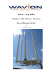
WBS-700 Mhz Outdoor Wi-Fi Base Station Installation Guide Rev.
Copyright Notice ©2010 Wavion, Inc. All rights reserved. Wavion is a registered trademark of Wavion in the United States and certain other jurisdictions. Specifications are subject to change without notice. FCC Notice to Users and Operators This equipment has been tested and found to comply with the limits for a Class B digital device, pursuant to Part 15 of the FCC Rules.
Contents Chapter 1 Chapter 2 Chapter 3 Chapter 4 Chapter 5 Chapter 6 Chapter 7 Chapter 8 3 About This Guide....................................................................... 4 Preface .................................................................................................. 4 Conventions ........................................................................................... 4 Contacting Technical Support .................................................................. 5 Introduction.
Chapter 1 About This Guide Preface This guide details the Wavion WBS-700 installation procedures. The intended audience of this document is trained technical professionals. Conventions The exclamation point within a triangle is intended to alert the user to the presence of important operating and maintenance (servicing) instructions in the literature accompanying the product.
Contacting Technical Support For technical support, contact Wavion using these methods: Address: Wavion Technical Support Wavion 5 Hamada Street, PO BOX 580 Yoqneam Illit, 20692 Israel Telephone: +972-4-9097343 Fax: +972-4-9097322 Email: support@wavionnetworks.com Web: www.wavionnetworks.
Introduction Chapter 2 Introduction WBS-700 a high capacity, IP services oriented Broadband Wireless access system. WBS-700 is a new category of Broadband Wireless Base Station designed from the ground up for metro-Wi-Fi deployments. The system employs wireless packet switched data technology to support high-speed IP services including fast Internet and Virtual Private Networks.
Package Content Chapter 3 Package Content Check that the package contains: Qty Description 1 WBS-700 outdoor unit with connections to external antennas 6 N-type to N-type RF cables 6 Antennas 2 CLAMPS 46-125 X 14 MM STST 1 POST CLAMP 1 1 1 24 24 24 1 Safety cable POE injector unit with wall mounting kit AC PLUG, US Screws 10-32 X 1/2" SOCKET CAP SCREW Lock Washers FLAT Washers LN tool , 4mm Allen wrench Sealing tape SCOTCH 130C Additional Equipment and Tools required for Installation Ethe
Addition tools and materials, including appropriate means (e.g. a pole) for installing the outdoor equipment. 1/4-inch flat blade screwdriver WARNING: ONLY experienced installation professionals who are familiar with local building and safety codes and, wherever applicable, are licensed by the appropriate government regulatory authorities should install outdoor units and antennas.
Chapter 4 Installing the Wavion WBS-700 Metro Base Station This guide explains how to safely install the Wavion WBS-700 Metro Base Station.
Important Safety Instructions WARNING: It is illegal to modify the construction of this product. Modifying the operating frequency or enhancing the transmit output power through the use of external amplifiers or other equipment is specifically disallowed by the "Telecommunications Act." WARNING: This device is for outdoor or indoor use with conditions that no harmful interference to authorized radio stations results from the operation of this device.
Caution Only UL listed parts and components will be used for installation. Use UL listed devices having an environmental rating equal to or better than the enclosure rating to close all unfilled openings. Caution To maintain Overvoltage (Installation) Category II, install a suitable surge suppressor device in the branch circuit to limit expected transients to Overvoltage Category II values.
Choosing a Location To ensure the optimal performance select the locations for the equipment using the following guidelines: The antenna (not-integrated on the front panel of the outdoor unit) should provide a direct, or near line of sight, with the sector location that need to be covered. The antenna should be aligned to face the CPEs that aim to be in service, higher the placement of the antenna, the better the achievable link quality (but not in all cases).
Mounting Strategies Consider the available mounting structures and antenna clearance when choosing a mounting location. Wavion outdoor unit WBS-700 should always be mounted with the top of the unit parallel to the ground, and with the antennas pointing upward and clear of obstruction. It is recommended to attach ground and data cables to the WBS-700 prior to mounting. Before mounting the WBS-700, read the wiring instructions in Grounding the Wavion WBS-700 and Connecting Power and Data.
There are two pairs of threaded holes on the back of the unit, enabling to use the special clamps for mounting the unit on diverse pole diameters. Figure 4.
Mounting on a Pole/Streetlight WBS-700 can be mounted on a pole, tower, or streetlight. It is recommended to mount the WBS-700 on aluminum or galvanized steel structures. Note The Wavion WBS-700 must be mounted with the top of the unit parallel with the ground and with the antennas pointing upward. Note Before mounting the WBS-700, read the wiring instructions in Grounding the Wavion WBS-700 and Connecting a Data Port chapter. Metal/Wood/Streetlight Pole Mounting Figure 4.
Warning: Metal pole installation requires that the antennas are higher than the top of the pole. Note Antennas must be higher than the top of the metal pole and clear of any obstructions Note Mounting to wood, concrete, or painted poles requires primary grounding for the unit. Check the national electrical codes in your area for specific rules. To mount the Wavion WBS-700 on a metal/wood/streetlight pole: 1. Choose a mounting location.
5. Attach safety cable to protect installed unit Figure 4.
6. Use a torque wrench click type or digital set to 10 ft-lb, put a layer of loctite 242 type on the screws surface and torque all 4 screws. Re- torque to 15 ft-lb Figure 4.6 Use a torque wrench click Note: The WBS-700 unit must be parallel to the ground. The unit can be rotated to obtain the correct position. Note Installations on large wooden poles require band clamps such as those supplied by Panduit, www.panduit.com.
7. Grounding WBS-700. Figure 4.7 Grounding Method Caution: You must always install an external grounding wire. You must also ground the outdoor data protection device to a ground rod or a bonded pipe. Make sure you have completed grounding before you connect power to the WBS-700.
2. Connect the other end of the grounding cable to a good ground (earth) connection. (For example, a grounding rod). Figure 4.8 Grounding Grounding the Data Protection Device The grounding method for an indoor data protection device is shown in Figure 4.9. To ground an indoor data protection device: 1. Position the protection device as close to the building entrance as possible. 2. Attach a length of #10 AWG bare copper wires to the ground post on the data protection device. 3.
Figure 4.
Connecting Antennas This section explains how to connect the six antennas to the WBS-700X. In order for the WBS-700 to work properly, six antennas must be connected. Use 6 RF cables to connect all 6 Antennas to the unit body. Each RF cable has two sides with right angle and straight N-type connectors. Connect straight N-type to the antenna and right angle N-type to the unit body. Figure 4.
Figure 4.12 Connecting right angle N-Type connector to the antenna Figure 4.
WARNING: Only connect the unit to the power supply once all the antennas are connected. WARNING: Use caution when connecting the antennas. Undue haste can damage the unit. WARNING: Do not screw in the antenna when holding the top section of the antenna. You will most likely damage the antenna. WARNING: The installation should be done after connecting the antennas. After installation, the user should connect the antennas.
Antenna Sealing The following describes antenna sealing procedure Caution: It is important to read carefully this procedure and perform all its steps to ensure maximal moisture protection. Sealing Technique: After the antenna is connected, use isolation material to cover the N-Type connectors Apply the tape with tacky side up on the antenna and N-Type connector. Stretch and lapped sealing tape to form smooth, void-free splice Figure 4.
Connecting Power and DATA The following describes how to apply power and data to the WBS-700 Caution: You must always install an external grounding wire. Perform a simple continuity check between the WBS-700and the ground termination point to confirm. You must also ground the outdoor data protection device to a ground rod or a bonded pipe. Make sure you have completed grounding before you connect power to the WBS-700. The Wavion WBS-700 is equipped with two RJ45 connectors.
WARNING: The shields of the Cat5 cable must be properly terminated and bonded to the unit and to the protective earth (PE) at the building entrance. This provides protection against the risk of fire, electrical hazard and ensures the reliable operation of this equipment. Note: National Electrical Codes (NEC) Article 800 requires the use of an Agency Listed (UL/CSA) Building Entrance Protector for all power and communications cables entering a building.
Step 1 Step 2 Step 1 and Step 2: Unscrew the plastic cap and the cap cover. Thread the Ethernet cable through the cap cover and the cap. Connect the Ethernet cable to the “ETH” port. Step 3 Step 4 Step 3 and Step 4: Screw the plastic cap; make sure it is well tightening. Furthermore screw the cap cover to ensure perfect sealing. It will ensure IP-67 compliance. Figure 4.16 Steps to connect the Ethernet cable.
POE port RJ45 Pin Descriptions Pin T/R Signal Color Description 1 T TXD+ Orange-White TX Data 10/100BaseT 2 R TXD- Orange TX Data 10/100BaseT 3 T RXD+ Green-White RX Data 10/100BaseT 4 R PoE+ Blue Power input, 55 VDC (+) 5 T PoE+ Blue-White Power input, 55 VDC (+) 6 R RXD- Green RX Data 10/100BaseT 7 T PoE- Brown-White Power input, 55 VDC (-) 8 R PoE- Brown Power input, 55 VDC (-) Installation Guide 29
Safety Information for the Wavion WBS-700 The Federal Communications Commission (FCC) with its action in ET Docket 96-8 has adopted a safety standard for human exposure to RF electromagnetic energy emitted by FCC certified equipment. Proper operation of the Wavion WBS-700according to the instructions found in this manual, results in user exposure that is substantially below the FCC recommended limits.
Chapter 5 Product Specification WBS-700 The tables in this chapter contain specifications for the Wavion WBS-700. Physical Specifications Network Interfaces Auto-sensing 10/100 Ethernet Input from Wavion Injector Power Input Power from a Wavion POE Injector. Indicator Lights Ethernet port LED Link/Act indicator System Status LED indicator RF channel status indicator Physical Dimensions Antenna Array Diameter: 650mm Antenna Height: 1120mm Weight: 9.
Environmental Specifications Operating Temperature Range -40°C to +55°C (without sun shield) -40°C to +60°C (with sun shield) Storage Temperature Range -45°C to +85°C Weather Rating IP67 Wind Survivability 165 mph Salt and Fog Rust Resistance MIL-STD-810F 509.4 Shock and Vibration ESTI 300-192-4 spec T41.
Chapter 6 Installation Accessories This chapter describes the accessories available for the WBS-700 and ordering information. The following topics are covered in this chapter: Ethernet Cables Lightning Protection Power Over Ethernet Ethernet Cables Description Manufacturer Part Number Distributor Contact Information Outdoor CAT5e double jacket 4-pair data cable Teldor 8393204101 G.
Chapter 7 Wind Loading Considerations This chapter describes wind loading considerations for the WBS-700. Note: It is recommended to evaluate the static and dynamic load bearing capabilities for each assembly and installation individually. It is your responsibility to evaluate the load bearing capabilities of the structure. The Wavion WBS-700 weighs approximately 22 lbs, including all mounting hardware.
Chapter 8 Acronyms Acronym Description 2P Two-Phase or Split Phase 2W Two-Wire 3W Three-Wire AC Alternating Current ANSI American National Standards Institute AWG American Wire Gauge C Celsius CAT Category CCK Complementary Code Keying CFR Code of Federal Regulations CSA Canadian Standard Association dB Decibels dBi Decibels Relative to an Isotropic Radiator DBPSK Differential-Binary Phase-Shift Keying DC Direct Current DQPSK Differential-Quadrature Phase-Shift Keying DSSS
MHz Megahertz MIL-STD Military Standard N Neutral NEC National Electrical Codes NEMA National Electrical Manufacturers Association OFDM Orthogonal Frequency Division Multiplexing P Phase PE Protective Earth PoE Power over Ethernet RJ45 Registered Jack 45 RSS Received Signal Strength Rx Receive RXD Receive Data TUV Technical Inspection Association Tx Transmit TXD Transmit Data UL Underwriters Laboratories VAC Voltage (Alternating Current) VCCI Voluntary Control Counci