
Owner's Manual

7
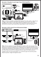
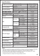
Example-4: RCA Input from Portable Audio Player
RCA OUT
RCA IN
+12V
GND
REM OUT
linkRC
(optional)
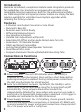
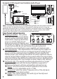
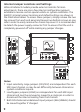
Top Panel Adjustments
ΠClipping Indicator: This yellow
LED indicates when the linkDQ’s
output reaches maximum signal
level before clipping (distortion)
occurs. It will be dimly lit just
before the onset of clipping, and
full bright at clipping. Since the linkDQ can produce up to 10Vrms,
its gain will usually be set well below this point while still
maximizing your amplifier(s) input capability at minimum gain.
Gain Adjustment: This adjustment is for matching the output of
the linkDQ with the maximum unclipped signal provided by your
source and the maximum input capability of your amplifier(s).
Follow proper gain setting procedures to ensure optimum source
volume range without clipping at any point within the signal chain
while minimizing the ability to overdrive the system. Readjustment
may be necessary after any changes to other level or EQ settings.
Ž Parametric EQ: This section provides adjustments for a single
parametric EQ band with the tuning flexibility required for
differences between vehicles, subwoofers and enclosures.
Boost: Sets the amount of boost applied at the center
frequency (Fc), adjustable up to +12dB.
Frequency: Sets the center frequency (Fc) of the EQ band,
adjustable from 30Hz to 80Hz.
‘ Width: This switch selects the width (Q) of the EQ band
between narrow and wide.
Note: Portable devices such as smartphones typically have an output voltage of
1Vrms or less. If using the device as the system’s volume control, it may be
necessary to adjust gain vs. volume range for consistent auto turn-on behavior.
For optimal signal range and convenient master volume control, the linkRC
remote level controller is recommended (sold separately).
Ž
‘
Œ
50
50