GARAGE DOORS & OPENERS 8300/8500 torsion windload MH installation instructions and owner’s manual Ta b l e o f C o nte nt s Pre-Installation Important Safety Instructions Tools Required Package Contents Door Section Identification Removing an Existing Door Preparing the Opening Installation Optional Installation Cleaning Your Garage Door Trolley Arm Hookup Side Lock Pull Rope Painting Your Garage Door Operation and Maintenance Warranty Dealer Locator Information 2 2 2 2 3 3 3 5 14 14 14 14 14 14 14
Pre-Installation Important Safety Instructions Tools Required Definition of key words used in this manual: • Power drill • Drill bits: 1/8”, 3/16”, 9/32”, 7/16”, 1/2” • Ratchet wrench • Socket driver: 7/16” • Sockets: 7/16”, 1/2”, 9/16”, 5/8” WARNING Indicates a potentially hazardous situation which; if not avoided, could result in severe or fatal injury. Caution: Property damage or injury can result from failure to follow instructions. Important: Required step for safe and proper door operation.
Weather seals & nails (If included) Inside/ Outside Step Plates Pull rope (if included) Operator bracket (if included) Lift Handles Rollers Side lock (as required) U-bars (as required) 1/4”- 20 Flanged (2) 5/16”-18 Hex nuts (2) 3/8”- 16 Hex nuts hex nuts (as required) 5/16” x 1 5/8” Hex head lag screws (as required) 6’0” 18” 18” 18” NA 18” 6’3” 21” 18” 18” NA 18” 6’6” 21” 18” 18” NA 21” 6’9” 21” 21” 18” NA 21” 7’0” 21” 21” 21” NA 21” 7’3” 24” 21” 21” NA 21” 7’6”
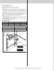
the mounting surface with nails. Weather seal (may not be included): Cut or trim the weather seal (if necessary) to the header and jambs. Note: If nailing product at 40°F or below, pre-drilling is required. For Q.I. track: Align the header seal with the inside edge of the header and temporarily secure it to the header with equally spaced nails. Next, fit the jamb seals up tight against the header seal and flush with the inside edge of the jamb. Temporarily secure the jamb seals with equally spaced nails.
1/4”- 20 Flange hex nut Installation Before installing your door, be certain that you have read and followed all of the instructions covered in the pre-installation section of this manual. Failure to do so may result in an improperly installed door. 1 JB-US jamb bracket Vertical track Attaching Q.I. Flag Angles to Vertical Tracks 1/4”- 20 x 9/16” Track bolt Jamb bracket in place Tools: None Horizontal Angles 4 Note: If you have F.A. flag angles, skip this step.
Repeat for other side. NOTE: Verify astragal (bottom seal) is aligned with door section. If there is more than 1/2” excess astragal on either side, trim astragal even with door section.
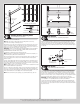
Bottom section inside 8300-8500 Windload Strutting Schedule—Windload Option Code 0132 5 Bottom Bottom section outside X Lock X Intermediate Intermediate II X Top X 8” Max. mounting height End hinge Intermediate hinge (2) 1/4”-20 x 5/8” Self drilling screws U-bar Holes enlarged to 7/16” diameter Pre-punched holes 10 U-bar (2) 1/4”-14 x 5/8” Self drilling screws between hinge locations Fasten u-bars at all end hinge and intermediate hinge locations, as well as locations between hinges.
Lock section Flag angle Vertical track Jamb bracket Bottom section 5/16” x 1-5/8” Lag screws Vertical tracks 12R FA 15R FA 12R QI 15R QI Flag angle lag screw locations 3/8” to 5/8” Spacing 1/4”-14 x 7/8” Self drilling screw locations Bottom section Vertical track 12 Left end hinge Stacking Sections/ Securing Jambs Tools: Power drill,7/16” Socket driver 13 Note: Refer to door section identification. Note: Make sure hinges are flipped down, when stacking another section on top.
WARNING Door width + 3-3/8” to 3-1/2” Do not raise door until horizontal tracks are secured at rear, as outlined in Step, Rear Support, or door could fall from overhead position causing severe or fatal injury. Flag angle Nail Top section Level the horizontal track assembly and bolt the horizontal angle to the first encountered slot in the flag angle using (1) 3/8”-16 x 3/4” truss head bolt and (1) 3/8”-16 hex nut. Repeat for other side.
If your windload option code is 0124, secure all of the door’s rollers with 7/16” push nuts by placing a push nut onto the end of each roller and sliding it toward the end hinge or bracket. Leave at least 1/4” of space between push nut and end hinge or bracket.
23 Left hand wound, black winding cone (right hand side) Nylon center bracket bushing Tools: Step Ladder, Locking Pliers, 3/8” Wrench Thread the counterbalance cable around the back side of the left cable drum and verify that there are no cable obstructions. Hook the cable into the drum. Slide the left hand cable drum against the left hand end bearing bracket and tighten the set screws in the drum to 14-15 ft. lbs. of torque (once set screws contact the tube, tighten screws one full turn).
26 Rear Support Tools: Ratchet wrench, Socket: 1/2” 5/8”, Wrench: 1/2” 5/8”, (2) Vice clamps, Tape measure, Level, Hammer, Step Ladder Raise the door until the top section and half of the next section are in a horizontal position. Do not raise door any further since rear of horizontal track is not yet supported. Vice clamps above third roller on both sides of door WARNING Raising door further can result in door falling and cause severe or fatal injury.
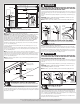
Sound framing members Perforated angle bolted using (2) 5/16” x 1-5/8” hex head lag screws to ceiling member and parallel to door Horizontal track (3) 5/16” Bolts and nuts Perforated angle 5/16”-18 x 1-1/4” Hex bolt must extend into the track to serve as a roller stop Sound framing members (3) 5/16” Bolts and nuts Horizontal track Perforated angle bolted using (2) 5/16” x 1-5/8” hex head lag screws to ceiling member and parallel to door Perforated angle 5/16”-18 x 1-1/4” Hex bolt must extend into
Optional Installation Trolley Arm Hookup Tools: Needle nose pliers NOTE: If Wayne-Dalton operator/ trolley bracket was installed, follow these directions. Align hole in the door arm with holes in operator bracket tabs, as shown. Attach with 5/16”-18 x 3-1/2” hex bolt, 3/8” washer and 5/16”-18 nut. Operator bracket tabs 5/16”-18 Nut Trolley arm 3/8” Washer 5/16”-18 x 3-1/2” Hex bolt Side Lock Tools: Power drill, 7/16” Socket driver, Tape measure Install the side lock on the second section of the door.
Opening a Door: Make sure the lock(s) are in the unlocked position. Lift the door by using the lift handles/ suitable gripping points only. Door should open with little resistance. Closing a Door: From inside the garage, pull door downward using lift handles/ gripping point only or a high friction area only. If you are unable to reach the lift handles/ suitable gripping points only, use pull rope affixed to the side of door. Door should close completely with little resistance.
Warranty Lifetime limited warranty Models 8300, 8500 Subject to the terms and conditions contained in this Lifetime Limited Warranty, Wayne-Dalton Corp.
Covered by one or more of the following Patents; 5,408,724; 5,409,051; 5,419,010; 5,495,640; 5,522,446; 5,562,141; 5,566,740; 5,568,672; 5,718,533; 6,019,269; 6,089,304; 6,644,378; 6,374,567; 6,561,256; 6,527,037; 6,640,872; 6,672,362; 6,725,898; 6,843,300; 6,915,573; 6,951,237; 7,014,386; 7,036,548; 7,059,380; 7,121,317; 7,128,123; 7,134,471; 7,134,472; 7,219,392; 7,254,868. Canadian: 2,384,936; 2,477,445; 2,495,175; 2,507,590; 2,530,701; 2,530,74; 2, 2,532,824.