GARAGE DOORS & OPENERS Double Flush, Model 44 To r s i o n 6” Front Mount Low Headroom MH installation instructions and owner’s manual Ta b l e O f C o n t e n t s Parts Breakdown Pre-Installation Important Safety Instructions Tools Required Package Contents Door Section Identification Graduated End Hinge And Strut Identification Removing an Existing Door Preparing the Opening Installation Optional Installation Door Arm Hookup Lift Handles Pull Down Rope Maintenance Cleaning Your Garage Door Painting
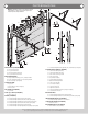
Parts Breakdown NOTE: The illustrations shown on this page are general representations of the door parts. Each specific door models may have unique variations. G5. G11. G7. H2. G9. G12. F1. G2. G1. G5. G3. G12. G6. H1. A1. G4. G9. D1. D1. A2. E1. G5. G10. G8. G4. D1. G5. C1. D1. A1. A2. F6. C2. F4. H2. F3. C2. F1. G13. F7. F2. C3. B3. F6. F4. B2. A2. B1. I1. A4. H1. A1. J1. F7. K1. A3. F3. G13. F5. J1. F2. F5. I1. A. Track Rollers (As Required): A1.
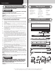
Pre-Installation Important Safety Instructions Tools Required Definition of key words used in this manual: • Power drill • Drill bits: 1/8”, 3/16”, 9/32”, 7/16”, 1/2” • Ratchet wrench • Socket driver: 7/16” • Sockets: 7/16”, 1/2”, 9/16”, 5/8” WARNING Indicates a potentially hazardous situation which; if not avoided, could result in severe or fatal injury. Caution: Property damage or injury can result from failure to follow instructions. Important: Required step for safe and proper door operation.
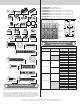
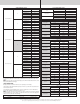
5/16” x 1-1/4” Clevis pin (as required) Cotter pin (as required) The BOTTOM SECTION can be identified by #1. The INTERMEDIATE I SECTION can be identified by #2. The INTERMEDIATE II SECTION can be identified by #3, for a 4 section high door only. The INTERMEDIATE III SECTION can be identified by #4, for a 5 section high door only. The INTERMEDIATE IV SECTION can be identified by #5, for a 6 section high door only. The INTERMEDIATE V SECTION can be identified by #6, for a 7 section high door only.
Graduated End Hinge Schedule Top 2” Intermediate IV 5# Intermediate III 4# Intermediate II 3# Intermediate I 2# Bottom 1# 6 Section High Door 3” 2” Top N/A Intermediate IV 7# Intermediate III 6# Intermediate II 5# Intermediate I 4# Bottom 3# Top N/A Intermediate V 6# Intermediate IV 5# Intermediate III 4# Intermediate II 3# Intermediate I 2# Bottom 1# Top N/A 7 Section High Door 3” 2” Intermediate V 8# Intermediate IV 7# Intermediate III 6# Intermediate II
7 Section High Strutting Schedule Intermediate IV Intermediate III Intermediate II (1) Long (1) Long Top Of Section N/A N/A Bottom Of section (1) Long (1) Long Top Of Section Bottom Of section N/A N/A (1) Long (1) Long Top Of Section N/A N/A Bottom Of section N/A (1) Long Top Of Section N/A N/A Bottom Of section Intermediate I Bottom N/A N/A Top Of Section (1) Short (1) Short Bottom Of section Preparing the Opening IMPORTANT: If you just removed your existing door or you are i
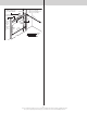
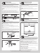
Suitable mounting surface 2”x 6” lumber minimum Min. side room clearance for 2” track is 3-1/2” (89 mm). Min. side room clearance for 3” track is 4-1/2” (114 mm). Headroom Header board 2”x 6” lumber preferred Min. side room clearance for 2” track is 3-1/2” (89 mm). Min. side room clearance for 3” track is 4-1/2” (114 mm).
Tools: Hammer, Tape Measure, Saw Horses Note: If a bottom weather seal is supplied, complete this step. Note: Refer to Door Section Identification / Parts Breakdown. Place the bottom section face down on a couple of sawhorses or flat clean/ smooth surface. Align the bottom weather seal with the flap pointing towards the outside surface of the bottom section.
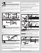
Starting on the left hand side, attach the upper slot of the graduated end hinge to the bottom section using (1) 1/4”-20 x 2-1/2” carriage bolt and (1) 1/4”–20 flange hex nut. Next, secure the lower slot of the graduated end hinge to the bottom section using (1) 1/4”-20 x 2-1/2” carriage bolt and (1) 1/4”–20 flange hex nut, as shown. Repeat same process for other side.
8 Half Center Hinges 10 Tools: Power drill, 7/16” Socket driver, Tape measure Note: If you don’t have half center hinges, then skip this step. Refer to Package Contents / Parts Breakdown, to determine if you have half center hinges. Using a tape measure, position the half center hinges equally spaced in between the center hinges and equally spaced in between the center hinges and the graduated end hinges. Position the holes of the lower hinge leaf onto the bottom section surface, as shown.
If you have 3” vertical tracks: Tighten lag screws, securing the bottom jamb bracket/bottom slot to jamb, maintain 1/2” to 3/4” spacing, between the bottom section and vertical track. Hang counterbalance lift cable over flag angle/wall angle. Repeat same process for other side.
Door width (2” Track) + 3-3/8” to 3-1/2” Top of flag angle or Top of wallangle assembly Starting on the left hand side, vertically align the top section of the door with the lower sections. Maintaining the top fixture(s) position, tighten the 1/4”-20 flange hex nuts or 1/4”-20 x 1-3/8” bolts and or 1/4”-14 x 1” lag screws to secure the top fixture(s) to the top section.
springs, must be positioned, as shown. With assistance, pick up the torsion spring assembly and slide one end of the torsion shaft through one end bearing bracket. Lay the middle of the torsion shaft into the center bracket. Slide the other end of the torsion shaft into the other end bearing bracket. Position the torsion shaft so that equal amounts of the shaft extend from each end bearing brackets. above the door, at the center.
Black cable drum (right hand side) Coupler halves Set screws and Lock nut Center coupler assembly (3) 3/8” - 16 x 1-3/4” Hex head screws and (3) 3/8” - 16 Nylon hex lock nut Red cable drum (left hand side) Torsion keyed shaft Coupler halves Center bearing bracket(s) Coupler assembly Center bearing Set collar Right hand wound, red winding cone Center (right hand side) bearing Key Center bearing inside torsion spring Set screws and Lock nut Center bearing Left hand wound, black winding cone Set col
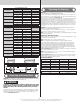
Center bearing brackets Coupler assembly Set screws Torsion keyed shaft Torsion keyed shaft (3) 3/8” - 16 nylon hex lock nuts 24 Coupler halves WARNING Torsion spring Left hand end bearing bracket Key Prior to winding or making adjustments to the springs, ensure you’re winding in the proper direction as stated in the Installation Instructions. Otherwise the spring fittings may release from spring if not wound in the proper direction and could result in severe or fatal injury.
WARNING Keep horizontal tracks parallel and within 3/4” to 7/8” maximum of door edge, otherwise door could fall, resulting in severe or fatal injury. Important: Do not support the weight of the door on any part of the rear back hangs that cantilevers 4” or more beyond a sound framing member. Note: If rear back hangs are to be installed over drywall, use (2) 5/16” x 2” hex head lag screws and make sure lag screws engage into solid structural lumber.
3/4” To 7/8” 3/4” To 7/8” Door edges Horizontal tracks Rear center back hang Horizontal track (1) 3/8” Truss head bolt (may not be supplied) (1) 3/8” Nut (may not be supplied) Horizontal track Drill 3/8” diameter hole Center of the horizontal track 26 Label Placement Tools: Step Ladder IMPORTANT: Using the illustration, attach the appropriate labels to the appropriate location on the section, as shown. NOTE: The Spring Warning tag(s) are factory attached (one per spring).
Optional Installation WARNING Door Arm Hookup Tools: Needle nose pliers Do not install pull down rope on doors with operators. Children may become entangled in the rope causing severe or fatal injury. At the center of the top section, measure horizontally from the top of center hinge to the bottom of strut. Using that dimension, measure and cut (2) pieces of perforated angles. Assemble the (2) pieces together using (2) 3/8” bolts and nuts (supplied by others).
Maintenance Before you begin, read all warning labels affixed to the door and the installation instructions and owner’s manual. When correctly installed, your Wayne-Dalton door will operate smoothly. Always operate your door with controlled movements. Do not slam your door or throw your door into the open position, this may cause damage to the door or its components. If your door has an electric opener, refer to the owner’s manual to disconnect the opener before performing manual door operation below.
3. Lubrication: The door should open and close smoothly. Ensure the door track rollers are rotating freely when opening and closing the door. If track rollers do not rotate freely, clean the door tracks, removing dirt and any foreign substances. Clean and lubricate (use a non-silicon based lubricant) graduated end hinges, steel track rollers, spring(s) and bearings. DO NOT lubricate plastic idler bearings, nylon track rollers, door track.
Warranty Limited warranty Double Flush, Model 44 Subject to the terms and conditions contained in this Limited Warranty, Wayne-Dalton (“Manufacturer”) warrants the sections of the door, against defects in material and workmanship, for a period of ONE (1) YEAR from the time of delivery provided: i) (i) The interior and exterior surfaces, as well as all edges of the wood door(s) are properly finished according to the Manufactures Maintenance and Painting Instructions and finish manufacturer’s instructions.
Covered by one or more of the following Patents; 5,408,724; 5,409,051; 5,419,010; 5,495,640; 5,522,446; 5,562,141; 5,566,740; 5,568,672; 5,718,533; 6,019,269; 6,089,304; 6,644,378; 6,374,567; 6,561,256; 6,527,037; 6,640,872; 6,672,362; 6,725,898; 6,843,300; 6,915,573; 6,951,237; 7,014,386; 7,036,548; 7,059,380; 7,121,317; 7,128,123; 7,134,471; 7,134,472; 7,219,392; 7,254,868. Canadian: 2,384,936; 2,477,445; 2,495,175; 2,507,590; 2,530,701; 2,530,74; 2, 2,532,824. Other US and Foreign Patents pending.