Ta b l e 8300/8500 To r s i o n Standard Lift and Light Commercial MH Installation Instructions And Owner’s Manual Please Do Not Return This Product To The Store Please Do Not Return This Product To The Store. Please call 1-866-569-3799 (Press Option 1) and follow the prompts to contact the appropriate customer service agent. They will be happy to handle any questions that you may have.
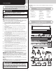
Pre-Installation Important: Right and left hand is always determined from inside the building looking out Important Safety Instructions Tools Required Definition of key words used in this manual: Warning WARNING • Power drill • Drill bits: 1/8”, 3/16”, 9/32”, 7/16”, 1/2” • Ratchet wrench • Socket driver: 7/16” • Sockets: 7/16”, 1/2”, 9/16”, 5/8” Indicates a potentially hazardous situation which; if not avoided, could result in severe or fatal injury.
Bottom corner brackets Bottom corner brackets Bottom corner brackets RH/LH (as required) RH/LH (as required) RH/LH (as required) 5/16” x 1 5/8” Hex head lag screws (as required) 3/8” Washers (as required) 5/16” x 2” Tamper-resistant hex head lag screw (as required) (1) Step plate (Inside) (2) Lift handles & spacers (1) Step plate (Outside) Strut clips (as required) Stud Plate (as required) Cotter ring (as required) Clevis pin (as required) 5/16” x 1-1/4” Clevis pin (as required) Cotter pin (as re
Type Of Sections Section Quantity 6 7 8 9 Intermediate(s) Section Door Height Bottom Lock Warning labels Top Int I Int II Int III Int IV Int V Int VI Intermediate I section 9’0” 18” 18” 18” 18” 18” 18” 9’3” 21” 18” 18” 18” 18” 18” 9’6” 21” 18” 18” 18” 18” 21” 9’9” 21” 21” 18” 18” 18” 21” 10’0” 21” 21” 18” 18” 21” 21” 10’2” 21” 21” 21” 18” 21” 21” 10’5” 21” 21” 21” 21” 21” 10’8” 21” 21” 21” 21” 21” 24” 11’0” 24” 21” 21” 21” 21” 24”
Wayne-Dalton dealer. Backroom requirement: Backroom is defined as the distance needed from the opening back into the garage to allow the door to open fully. *NOTE: For door heights from 10’1” to 14’0”, refer to your operator manufacture installation instructions for appropriate depth into room.
Parts Breakdown J3. NOTE: The illustrations shown on this page are general representations of the door parts. Each specific door models may have unique variations. J6. J8. J3. J6. J5. J2. J7. J5. J8. J4. J9. J6. J8. J7. A1. J6. F1. J5. J3. J1. G1. C1. F2. F3. J7. H1. B1. E1. G2. A2. A1. K1. I1. J1. J5. J3. J4. A2. J8. H2. F3. F1. F2. B2. C1. Top of vertical track Top of vertical track E2. B2. (Fully Adjustable Feature) 3rd hole set E3. I2. J2. E4. I4. I3. L1.
Installation Before installing your door, be certain that you have read and followed all of the instructions covered in the pre-installation section of this manual. Failure to do so may result in an improperly installed door. NOTE: Reference TDS 160 for general garage door terminology at www.dasma.com.
NOTE: The bottom jamb bracket is always the shortest bracket, while the center jamb bracket is the next tallest. If three jamb brackets per side are included with your door, you will have received a top jamb bracket, which is the tallest. To attach the bottom jamb bracket, locate lower hole of the hole/ slot pattern of the 1st hole set on the vertical track. Align the slot in the jamb bracket with the lower hole of the hole/ slot pattern.
graduated end hinges, center hinge(s) and strut (if applicable) are on top of their corresponding sections. INSTALLATION ON TOP SECTION: Place the strut on the top edge of the top section, as shown. Center the strut side to side on the section, as shown. Secure the graduated end and center hinges to the section using (2) 1/4” - 20 x 7/8” self drilling screws at each graduated end / center hinge locations.
Strutting Schedule For Model 8300 Aluminum (Brown Colored Doors) Door Heights Section Quantity Door Configurations Strutting Schedule For Model 8500 Steel (Brown Colored Doors) Door Widths 12’0” 16’0” 6’0” - 10’0” Solid / Top (Windows) 5 2S, TS Intermediate (Windows) > 8’0” Solid / Top (Windows) 6 2S, TS Intermediate (Windows) 3S, TS / 3S, I2 / 3S, I1 / 3S, BS 3S, TS / 3S, IW / 3S, I1 / 3S, BS 3S, TS / 3S, I2 / 3S, I1 / 3S, BS 3S, TS / 3S, IW / 3S, I1 / 3S, BS 17’0” 18’0” Door Heights 20’0” Se
Strutting Schedule For Model 8500 Aluminum (White, Almond & Taupe Colored Doors) Door Heights Door Section ConfiguQuantity rations Door Widths 6’0” 9’0” Solid 5 2S, TS Intermediate (Windows) 12’0” 14’0” 15’0” 16’0” 2S, TS / 2S, I1 2S, TS / 2S, I1 2S, TS / 2S, IW 2S, TS / 2S, I2 / 2S, I1 / 2S, BS 2S, TS Top (Windows) 2S, TS Intermediate (Windows) 20’0” (2) 1/4”-20 x 7/8” Self drilling screws Strut installation at top of section 2S, TS / 2S, I2 2S, TS / 2S, IW 2S, TS 3S, TS / 2S, I2 / 2S
Lock section outside Lock section inside 1/2” Diameter holes Lift handle 4” Lift handle (2) Spacers (2) 1/4”-20 x 2-1/2” Carriage bolts 10 Flag angle (2) 1/4”-20 Hex nuts Vertical track assembly Bottom Section Tools Required: Level, Wooden shims (if necessary) 5/16” x 1-5/8” Lag screws Jamb bracket Center the bottom section in the door opening. Level the section using wooden shims (if necessary) under the bottom section.
securing with 1/4” - 20 x 5/8” self-tapping screws. There should be no gap between the hinge leafs and the sections. NOTE: Install lock at this time (sold separately). See optional installation step, Side Lock.
Now, locate the center of the top section and align the center of the holes in the drawbar operator bracket assembly with the top section center line. Align the drawbar operator bracket assembly vertically. NOTE: For retro fit applications, the drawbar operator bracket assembly must be aligned with an existing operator. Slide the top halve of the drawbar operator bracket assembly under the strut, keeping the drawbar operator bracket assembly aligned with the center line.
NOTE: Prior to fastening center bracket(s) into the door jamb, pilot drill using a 3/16” drill bit. NOTE: Refer to Package Contents / Parts Breakdown, to determine if your door came with a coupler assembly. If your door came with a coupler assembly, the mounting surface needs to be a minimum of 17” wide. The two center bearing brackets will need to be spaced 12” to 14” apart at the center of the door, as shown.
Center of door Mounting surface (17” Minimum) † the torsion keyed shaft. Next on the right hand side, lay the other coupler half, center bearing, the torsion spring with the black winding cone, and the black cable drum at the right end of the torsion keyed shaft. Slide the coupler halves, center bearings onto the torsion keyed shafts followed by the torsion springs and the cable drums, as shown. IMPORTANT: The coupler halves, center bearings, torsion springs, cable drums must be positioned, as shown.
(3) 3/8” - 16 x 1-3/4” hex head screws and (3) 3/8” - 16 Hex nuts Equal spacing Left hand end bearing bracket Torsion keyed shafts Center bracket bushing Right hand end bearing bracket Stationary spring cone Center bracket Torsion spring Center bracket Torsion Spring Attachment 21 Tools Required: Step Ladder, Ratchet Wrench, 9/16” Socket, 9/16” Wrench 22 NOTE: Refer to Package Contents / Parts Breakdown, to determine which Center Bracket(s) came with your door.
Chalking Torsion Spring(s) 23 Warning WARNING Tools Required: Step Ladder, Chalk Use only specified winding bars, as stated in Step Securing Door for Spring Winding. DO NOT SUBSTITUTE with screwdrivers, pipe, etc. Other tools may fail or release from the spring cone and cause serious personal injury. Draw a chalk line horizontally along the center of the torsion spring coil(s). As the torsion spring is wound, the chalk line will create a spiral.
1.) Check the door for level. 2.) Check the torsion shaft for level. 3.) Check the track spacing. 4.) Check the counterbalance cables for equal tension and proper wrap onto the cable drums. 5.) Check the track for potential obstruction of the track rollers. 6.) Clamp locking pliers onto track and rewind springs. IMPORTANT: If door still does not operate properly, then contact a trained door system technician. Warning WARNING Raising door further can result in door falling and cause severe or fatal injury.
Sound framing members (3) 5/16” Bolts and nuts Horizontal track Perforated angle bolted using (2) 5/16” x 1-5/8” hex head lag screws to ceiling member and parallel to door Perforated angle 5/16”-18 x 1-1/4” Hex bolt must extend into the track to serve as a roller stop 3/4” To 7/8” Door edges Horizontal tracks 3/4” To 7/8” 20
Optional Installation Trolley Arm Hookup NOTE: If Wayne-Dalton operator / trolley bracket was installed, follow these directions. Align hole in the door arm with holes in operator bracket tabs, as shown. Attach with 5/16” x 1-3/4” cotter pin and cotter ring. Drawbar operator bracket tabs 5/16” x 1-3/4” Clevis pin Cotter ring 5/16” x 1-3/4” Clevis pin Cotter ring Door arm Inside Lock Install the inside lock on the second section of the door.
Maintenance Always operate your door with controlled movements. Do not slam your door or throw your door into the open position, this may cause damage to the door or its components. If your door has an electric opener, refer to the owner’s manual to disconnect the opener before performing manual door operation below. Manual door operation: For additional information on manual garage door operations go to www.dasma.com and reference TDS 165.
and owner’s manual. If in question about any of the procedures, do not perform the work. Instead, have it adjusted by a trained door systems technician. 3. Lubrication: The door should open and close smoothly. Ensure the door track rollers are rotating freely when opening and closing the door. If track rollers do not rotate freely, clean the door tracks, removing dirt and any foreign substances.
Warranty Limited Warranty Models 8300 and 8500 Wayne Dalton, a division of Overhead Door Corporation (“Seller”) warrants to the original purchaser of the Models 8300 and 8500 (“Product”), subject to all of the terms and conditions hereof, that the Product and all components thereof will be free from defects in materials and workmanship for the following period(s) of time, measured from the date of installation: Limited Lifetime Warranty* on the Product sections against: • The Product becoming inoperable due
Thank you for your purchase. Please Do Not Return This Product To The Store Please Do Not Return This Product To The Store. Please call 1-866-569-3799 (Press Option 1) and follow the prompts to contact the appropriate customer service agent. They will be happy to handle any questions that you may have. After installation is complete, fasten this manual near garage door for easy reference.