INSTALLATION INSTRUCTIONS AND OWNER’S MANUAL ® GARAGE DOOR OPENER Chain/ Belt Drive Models: 3220C, 3221C, 3222C, 3224C, 3320B, 3322B, 3324B 3220C-Z, 3221C-Z, 3222C-Z, 3224C-Z, 3320B-Z, 3322B-Z, 3324B-Z FOR RESIDENTIAL SECTIONAL OVERHEAD GARAGE DOORS ONLY! DO NOT USE ON ONE PIECE DOORS! IMPORTANT! THE DOOR AND OPENER WILL NOT FUNCTION PROPERLY UNTIL INFRARED SAFETY SENSORS ARE INSTALLED AND PROPERLY ADJUSTED! IMPORTANT NOTICE! Read the enclosed instructions carefully before installing/operating this gara
NOTE: Depending on the opener model, some parts listed may not be supplied.
PRE-INSTALLATION INSPECTION OF YOUR GARAGE DOOR PRIOR TO PRODRIVE ® OPENER INSTALLATION To ensure your new Prodrive ® opener works as intended, your garage door must be properly installed and balanced. Before installing your garage door opener, open and close you door manually to ensure it operates smoothly from top to bottom. A properly balanced door should not take a lot of effort to open or close by hand. The door should stay in the open and in the closed position without drifting down or creeping up.
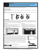
Pre-Installation IMPORTANT! Before starting the installation read these instructions thoroughly to familiarize yourself with all aspects of installation and adjustment. IMPORTANT: IF YOUR GARAGE HAS NO SERVICE ENTRANCE DOOR, INSTALL AN OPTIONAL OUTSIDE QUICK RELEASE LOCK. THIS ACCESSORY ALLOWS MANUAL OPERATION OF GARAGE DOOR FROM OUTSIDE IN CASE OF POWER FAILURE. IDENTIFY YOUR DOOR Identify your door by referring to illustrations below and verify that your door type is a sectional door with curved track.
System Features 1. Open and Close Cycle Control: Allows garage door to be started and stopped by push button, transmitter or wall station. The next impulse sends a stopped garage door in opposite direction. 2. Emergency Disconnect: Manual disconnect permitting operation of door during power failure with automatic reconnect when opener is reactivated. See page 27. 3. Opener light: Automatically turns on when opener is activated and remains on for four minutes for convenience and safety. 4.
Table of Contents Package Contents ..............................................................................I. Pre-Installation Inspection ............................................................. II, III Tools Needed ...................................................................................IV. Important Safety Instructions ............................................................V. Prodrive ® Installation ..................................................................1-5.
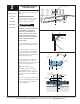
Tools Needed: 3/8” Socket Ratchet Wrench Attaching Opener to Rail Rail Bottom (Facing Upwards) Sprocket / Coupling Cogs IMPORTANT: THE DRIVER GEAR IN THE OPENER MUST BE PROPERLY ALIGNED WITH THE SPROCKET/ COUPLING COGS IN THE RAIL ASSEMBLY AND THE MOUNTING BOLTS FULLY TIGHTENED, BEFORE POWERING UP THE OPENER. NEGLECTING TO DO THIS WILL RESULT IN GEAR FAILURE. INSTALLATION 1 Notches Before assembly, align sprocket/ coupling cogs to match notches of driver gear.
2 Positioning and Installing Front Wall Bracket Tools Needed: Carpenter’s Level 7/16” Socket Driver Power Drill Tape Measure 1/8” Drill Bit Reinforce with 2” x 6” as required to insure rigid mounting. NOTE: It is recommended that the door opener be installed 7 feet or more above the garage floor. REINFORCE THE HEADER WALL Reinforce the header wall (wall above door opening) as required, to ensure rigid mounting of the front wall bracket.
3 Tools Needed: 7/16” Socket Ratchet Wrench Adjustable Wrench Front Wall Bracket Attach Unit to Front Wall Bracket Raise the front end of the rail assembly and attach it to the front wall bracket, using the 1/4” x 4” hex head bolt and the supplied 1/4” plastic insert locking nut. Take care not to over tighten nut. Tighten only until end of bolt is flush with outside of nut.
5 Mounting Opener End Tools Needed: CAUTION: Do not use gear cap bolt or nut Ceiling Joist for hanger attachment. This may cause sprocket, chain or Belt misalignment, resulting in damage to opener or possible personal injury! Power Drill Hacksaw 1/8” Drill Bit Align the center of opener’s rail assembly with the center line previously marked on the top section of the garage door to ensure rail will be parallel with the direction of door travel.
6 Tools Needed: 7/16” Socket Ratchet Wrench Reinforce Door Vertically and Horizontally Mounting Door Bracket NOTE: If you have a 5120, 5140, 9100, 9400, 9600, 9700 or 9800 series door, do not install this door bracket, install the door bracket supplied with the door, see the Installation Instructions and Owner’s Manual supplied with the door. Instructions manuals are available for download at www.waynedalton.com or call 1-888-827-3667.
8 Tools Needed: Power Drill Phillips Head Screwdriver Flat Tip Screwdriver 3/32” Drill Bit Wired Wall Station Installation (If Included) Wall Station WARNING TO PREVENT POSSIBLE INJURY, INSTALL WALL STATION OUT OF THE REACH OF CHILDREN AND IN A LOCATION WHERE THE DOOR CAN BE SEEN WHEN THE OPENER IS ACTIVATED. DO NOT MOUNT WALL STATION NEAR OR NEXT TO GARAGE DOOR. 5 Foot Minimum IMPORTANT: THE STANDARD PUSH BUTTON OR THE DELUXE WALL STATION MUST BE THE ONLY TYPE USED FOR PROPER DOOR OPERATION.
9 Tools Needed: Power Drill 3/32” Drill Bit Phillips Head Screwdriver Deluxe Multi-Function Wireless Wall Station Installation (If Included) WARNING TO PREVENT POSSIBLE INJURY, INSTALL WALL STATION OUT OF THE REACH OF CHILDREN AND IN A LOCATION WHERE THE DOOR CAN BE SEEN WHEN THE OPENER IS ACTIVATED. DO NOT MOUNT WALL STATION NEAR OR NEXT TO GARAGE DOOR. Wall Station 5 Foot Minimum NOTE: For proper operation, mount the wall station on a flat surface.
Deluxe Multi-Function Wireless Wall Station Installation Continued (If Included) To Operate Pr e He ss re oo Up/Down LED D r Remove the battery cover (right-hand side of wall station) by disengaging the battery cover’s lower clip. Install two AAA batteries into the wall station observing the polarity, (+) and (-), of both batteries. After about three seconds, the red LED will begin to blink every three seconds.
11 Tools Needed: Wired Infrared Safety Sensor Installation Ratchet Wrench IMPORTANT: BOTH WALL BRACKETS MUST BE MOUNTED AT THE SAME HEIGHT FOR PROPER ALIGNMENT. Tape Measure Note: Use Steps a-c for installing sensors on both sides of the garage door. Power Drill 3/16” Drill Bit 7/16” Socket Driver 7/16” Wrench Pencil a. Select and mark with a pencil, a mounting location no more than 5 inches above the floor to center line of wall mounting bracket.
12 Installation of Wiring for Wired Infrared Safety Sensor Tools Needed: Uncoil the wires from the infrared safety sensors and route the wire up the garage wall across the ceiling and down to the back of the opener. Tack the wires in place using staples (Not Supplied). Take care to run the wires in a location where they will not interfere with the operation of the door and do not staple through wire.
14 Tools Needed: None Connecting Opener To Outlet WARNING TO REDUCE THE RISK OF ELECTRICAL SHOCK, DO NOT CHANGE THE POWER CORD IN ANYWAY. Outlet IMPORTANT: THE OPENER MUST BE CONNECTED TO A PROPERLY GROUNDED 3 PRONG, 120 VOLT OUTLET. The opener can be permanently wired. To permanently wire the unit, see permanent wiring option on page 20. Plug the power cord into the closest grounding type receptacle. Excess power cord length must be routed and contained safely away from any moving parts.
16 Tools Needed: Pliers Alignment of Wired Infrared Safety Sensors WARNING In In Out Out TO AVOID POSSIBLE SEVERE OR FATAL INJURY, KEEP PEOPLE AND OBJECTS CLEAR OF THE MOVING DOOR ARM TO PREVENT POSSIBLE PERSONAL INJURY. IMPORTANT: THE SAFETY SENSOR SENDS AN INVISIBLE BEAM OF LIGHT FROM THE SENDING UNIT TO THE RECEIVING UNIT ACROSS THE PATHWAY OF THE DOOR. THE OPENER WILL NOT OPERATE UNTIL THE SAFETY SENSORS ARE CONNECTED TO THE OPENER AND PROPERLY ALIGNED.
17 Tools Needed: Single and Double Tab Door Brackets Setting Trolley Close Position Models: 9100, 9400, 9600, 5120 and 5140. Model: 9700 WARNING Pliers/Wire Cutters TO AVOID POSSIBLE INJURY OR Tape Measure Flat Tip Screwdriver PROPERTY DAMAGE, KEEP PEOPLE AND OBJECTS CLEAR OF THE MOVING DOOR ARM. NOTE: If necessary, activate the opener to move the trolley/ upper door arm to the closed position.
18 Typical Installation Connecting Door Arm to Door 5/16” x 1-1/4” Multi-grip Clevis pin Door Bracket Nylon Shoulder Bushing Tools Needed: Typical Installation: Place nylon shoulder bushing in lower arm Adjustable Wrench hole in curved end (single hole). Place door arm on right side of door bracket. Insert Ratchet Wrench 5/16” x 1-1/4” multi-grip clevis pin through nylon shoulder bushing, lower door arm and middle hole of door bracket.
19 Tools Needed: Flat Tip Screwdriver Setting Door Close Travel Using the wall control up/down button, activate door to full open position; reactivate to close position. Bottom Of Opener The door should stop on the floor with the bottom door seal slightly compressed. If the door reverses off the floor, turn close travel knob 1/4 turn “less”. If door is not completely closed, turn travel knob 1/4 turn “more”. Repeat as necessary. NOTE: 1/4 turn equals 1” of door travel.
Setting Door Opening Travel (Continued) NOTE: If door does not open fully and opener light flashes (make sure the bulb is installed and operating) check for an obstruction or see Adjustment #1, page 32 (Adjusting Opening Force). To adjust for a non-standard door or to precisely set the open position: Using the wall station, operate the door and stop it in mid-travel position. Using a flathead screwdriver turn the OPEN travel adjuster for more (counter-clockwise) or less (clockwise) travel.
21 Tools Needed: 2 x 4 Board Contact Obstruction Test After installing the opener, the door must reverse when it contacts a 1 1/2” inch high object (or a 2 x 4 board laid flat) on the garage floor. Using the wall station, activate the door to the fully open position. Place a 2 x 4 flat on the garage floor, under the door path. Activate the door to the closed position with the wall station. Upon contacting the 2 x 4 board, the door should reverse.
23 Tools Needed: None Programming Wireless Keyless Entry (If Included) WARNING DURING PROGRAMMING THE GARAGE DOOR MAY OPERATE. KEEP PEOPLE AND OBJECTS CLEAR OF THE MOVING DOOR TO PREVENT DOOR DAMAGE OR POSSIBLE PERSONAL INJURY. Right Side Of Opener NOTE: To simplify installation, program the wireless keyless entry to the opener before mounting to the wall. Program Status LED 2. Press the desired five digit PIN (PERSONAL IDENTIFICATION NUMBER), example 1-3-8-2-5.
24 Tools Needed: Power Drill Installing Wireless Keyless Entry (If Included) IMPORTANT: INSTALL ALL WALL CONTROLS OUT OF THE REACH OF CHILDREN AND IN A LOCATION WHERE THE DOOR CAN BE SEEN BEFORE ACTIVATING. Keyless Entry 5/64” Drill Bit Phillips Head Screwdriver Locate a convenient place to mount the wireless keyless entry, that does not interfere with the normal opening and closing of the door. To keep keyless entry out of the reach of children, measure and mark a spot at least 5 feet up from the floor.
I Power Connection (Permanent Wiring Option) Tools Needed: WARNING Needle Nose Pliers Pliers/Wire Cutters Flat Tip Screwdriver Power Cord 1/2” To 1” Opener Strain Relief Bushing TO AVOID ELECTRICAL SHOCK, DISCONNECT POWER AT THE FUSE/ BREAKER BOX BEFORE PROCEEDING. IMPORTANT: CHECK YOUR LOCAL ELECTRICAL CODES. IF YOUR LOCAL CODE REQUIRES PERMANENT WIRING, USE THE SPECIFICATIONS CALLED FOR AND INSTRUCTIONS ILLUSTRATED. Permanent Wiring Procedure 1.
Tools Needed: Power Drill 7/16” Socket Driver Door Bracket IMPORTANT: WHEN CONNECTING A TROLLEY TYPE GARAGE DOOR OPENER TO A 9700 SERIES DOOR, A WAYNEDALTON OPENER/TROLLEY BRACKET MUST BE SECURELY ATTACHED TO THE TOP SECTION OF THE DOOR, ALONG WITH ANY U-BARS PROVIDED WITH THE DOOR. THE INSTALLATION OF THE OPENER MUST BE ACCORDING TO MANUFACTURER’S INSTRUCTIONS AND FORCE SETTINGS MUST BE ADJUSTED PROPERLY. Locate the center of the top section or factory attached u-bar as shown in FIG 1.1.
I Tools Needed: Power Drill 7/16” Socket Driver Vice Clamps Phillips Head Screwdriver Mounting Door Bracket To A (9100, 9400, 9600, 5120 & 5140 Series Door) IMPORTANT: WHEN CONNECTING A TROLLEY TYPE GARAGE DOOR OPENER TO THE ABOVE LISTED DOORS, A WAYNEDALTON OPENER/TROLLEY BRACKET MUST BE SECURELY ATTACHED TO THE TOP SECTION OF THE DOOR, ALONG WITH ANY U-BARS PROVIDED WITH THE DOOR.
I Tools Needed: Setting Trolley Close Position/ Connecting Door Arm Horizontal Track (Models 9100, 9400, 9600, 5120, 5140 & 9700) With TorqueMaster® Or Extension Springs Horizontal Track 12” OR 15” DETERMINE THE WAYNE-DALTON TRACK RADIUS BEING USED: FIG. 1 12” Needle Nose Pliers FOR MOUNT HOPE AND PENSACOLA TRACK: Adjustable Wrench Measure the curved ends of the horizontal track to determine if you have a 12” or 15” radius horizontal track, as shown in FIG. 1.
Setting Trolley Close Position/ Connecting Door Arm (Continued) LOW HEADROOM: Using the LOW HEADROOM TROLLEY POSITIONING CHARTS, refer to DIM “X” to set the distance from header to trolley, as shown in FIG. 1.6. TRAVEL ADJUSTMENT OPEN MORE CLOSE LESS Bottom Of Opener MORE FIG. 1.5 NOTE: Depending on your setup, you may or may not have to cut straight arm to accomplish trolley settings.
I Tools Needed: Setting Trolley Close Position/ Connecting Door Arm Horizontal Track (Models 9100, 9400, 9600, 5120, 5140 & 9700) With Torsion Springs DETERMINE THE WAYNE-DALTON TRACK RADIUS BEING USED: FIG. 1 12” Clevis Pin Trolley 12” “X” 10”, 12”, 14”, OR 15” Standard Lift Track Top Section FIG. 1.2 STANDARD LIFT: Using the STANDARD LIFT TROLLEY POSITIONING CHARTS, refer to DIM “X” to set the distance from header to trolley, as shown in FIG. 1.2.
Setting Trolley Close Position/ Connecting Door Arm (Continued) LOW HEADROOM: Using the LOW HEADROOM TROLLEY POSITIONING CHART, refer to DIM “X” to set the distance from header to trolley, as shown in FIG. 1.5. TRAVEL ADJUSTMENT OPEN MORE LESS CLOSE FIG. 1.4 NOTE: Depending on your setup, you may or may not have to cut straight arm to accomplish trolley settings. If adjustment of the trolley position is required, use the close travel adjustment screw located on the bottom of the opener.
IMPORTANT SAFETY INSTRUCTIONS 1. READ AND FOLLOW ALL INSTRUCTIONS. 2. Never let children operate or play with the door controls. Keep remote controls away from children. 3. Always keep a moving door in sight and keep people and objects away until it is completely closed. NO ONE SHOULD CROSS THE PATH OF A MOVING DOOR. 4. NEVER GO UNDER A STOPPED, PARTIALLY OPEN DOOR. 5. Test the Door/Opener monthly.
I Operating the Wireless Wall Station Up-Down Button: Backlit LED Light: Momentarily pressing the Up/Down button starts or stops door movement or changes door’s direction. Pressing and holding Up/ Down button during the door’s travel will override safety sensors. The Up/Down Button (when unit is closed) can be activated by pressing flip cover. The red LED blinks intermittently to help you locate the wall station in a dark garage.
I Customizing the Settings Custom pet position: The pet button opens a closed door to a preset position between 8 and 30 inches above the floor, allowing pets to enter and exit the garage without the door being fully open. To change the automatic pet opening height: Start with the door in the closed position. 1. Operate the door then stop it at the desired height. If desired height is not achieved, the door must be returned to the closed position. 2.
I Primary Programming for HomeLink® to the Prodrive ® NOTE: This step can only be done on automobiles equipped with the HomeLink® System. NOTE: Programming HomeLink® requires a Wayne-Dalton Transmitter that is programmed to the opener (the wallstation and transmitter(s) supplied with the opener, come pre-programmed from the factory). Any additional wallstation(s) or transmitter(s) will need to be programmed to the opener, see page 33.
I Alternate Programming for HomeLink® to the Prodrive ® NOTE: This Step can only be done on automobiles equipped with the HomeLink® System. Programming/Training HomeLink® Unit NOTE: Programming HomeLink® requires a Wayne-Dalton Transmitter that is programmed to the opener (the wallstation and transmitter(s) supplied with the opener, come pre-programmed from the factory). Any additional wallstation(s) or transmitter(s) will need to be programmed to the opener, see page 33.
I Adjustments Adjustment # 1 Opening and Closing Force This garage door opener is built with a safety system that allows the door to reverse when closing and stop when opening. This must be adjusted so your opener does not use excessive force in the down direction or react to the weight of the door during upward travel. STATUS SW To adjust the closing force follow one of the two methods listed below. Method A (manual) 1. Turn the FORCE ADJ.
DURING PROGRAMMING THE GARAGE DOOR MAY OPERATE. KEEP PEOPLE AND OBJECTS CLEAR OF THE MOVING DOOR TO PREVENT DOOR DAMAGE OR POSSIBLE PERSONAL INJURY. Program Button FORCE ADJ. NOTE: The opener can be activated by up to 8 remote STATUS NOTE: Programming failure can occur if the wall station or transmitter is too close to the opener during the programming sequence. There must be a minimum of 6 feet between the wall station/ transmitter and the opener.
I Maintenance Monthly Maintenance: 1. Lubricate hinges and rollers of garage door. Twice a Year: Check chain tension. If chain rests on bottom of rail, adjust tension by 2. Inspect the door for loose fasteners, worn or frayed counterbalance turning the two chain adjusting nuts at the end of the rails cables and the presences of legible safety labels/ tags. Have repairs (opposite the opener end) clockwise.
Troubleshooting SYMPTOM Opener won’t work from wall button or radio control. PROBABLE CAUSE CORRECTIVE ACTION No power to opener. Check cord to outlet, wall switch and circuit breaker. Short circuit in wires to opener or wall button. Isolate by disconnecting the wires at the opener from the wall station. Motor Protector trips open due to excessive use. Allow motor to cool for 20 minutes and try again. Opener works from wall button but not from radio control.
Parts Breakdown Rail Assembly - All Models 22 9 3 22 30 1b 7b 3 7a 1a 12 22 4 2b 13 13 29 22 10 23 14a 20 2a 22 4 11a 26 25 11b 14b 18a 18b 21 5 19 8 24 4 26 22 8 1b 32 28 31 24 15 6 1a 22 22 17 26 16 27 #. Part # Description # Per Unit #. Part # Description # Per Unit 1a. 325756 R.H. Rail (7’) 1 12. 220959 Front Wall Bracket 1 325758 R.H. Rail (8’) 1 13. 157559 1/4” - 20 x 4” Hex Head Bolt w/ Lock Nut 1 325760 R.H. Rail (10’) 1 14a.
Parts Breakdown Opener Assembly And Accessories - All Models 4 12 13 15 8 5 1 16 15 7 14 3 15 27 28 11 20 19 21 9 17 22 To Operate Pr e He s s re D oo r 18 28 29 6 23 25 2 24 26 #. Part # Description # Per Unit #. Part # Description # Per Unit 1. 157167 Frame 1 16. 301675 Capacitor Clamp 1 2. 325017 Motor 1/2 HP 1 17. 252118 Wired Infrared Safety Sensor Kit 1 3. 306131 Motor Control Board 1 18. 252092 Limit Assembly 1 4.
Prodrive® Accessories Three Button Mini / Visor Transmitter Controls up to 6 doors or wireless accessories. Includes visor clip. Wired Deluxe Wall Station Allows independent door up/down control and overhead light on/off control. To Pr e He s s re r oo Wireless Keyless Entry Operate D Wireless Multi-Function RF Wallstation 10 digit numeric keypad which allows the operation of the garage door opener from outside by entering a programmable personal code on a keypad.
Cut-Out Template to Aid Installation DRILL TEMPLATE Pre-drill 3/32” pilot hole Multifunction Wall Station Template Pre-drill 5/64” pilot hole 5 Button Keyless Entry Template Please Do Not Return This Product To The Store. Call Us Directly! Our Trained Technicians Will Answer Your Questions and/or Ship Any Parts You May Need 39 You can reach us Toll Free at 1-888-827-3667 for Consumer Assistance or online at www.wayne-dalton.
Please Do Not Return This Product To The Store Call Us Directly! Our Trained Technicians Will Answer Your Questions and /or Ship Any Parts You May Need Call Us Toll-Free: (888) 827-3667 Thank you for your purchase www.wayne-dalton.com 40 Please Do Not Return This Product To The Store. Call Us Directly! Our Trained Technicians Will Answer Your Questions and/or Ship Any Parts You May Need You can reach us Toll Free at 1-888-827-3667 for Consumer Assistance or online at www.wayne-dalton.
® GARAGE DOOR OPENER LIFETIME LIMITED WARRANTY The Manufacturer warrants that the Prodrive® Garage Door Opener’s electronic and mechanical components (excluding motor) will be free from defects in materials and workmanship for a period of ONE YEAR (Models 3220C, 3221C, 3222C, 3320B, 3322B, 3220C-Z, 3221C-Z, 3222C-Z, 3320B-Z, 3322B-Z) and FIVE YEARS (Models 3224C, 3324B, 3224C-Z, 3324B-Z) from the date of installation, provided it is properly installed, maintained and cared for under specified use and serv
Patent Information Models: 3220C, 3221C, 3222C, 3224C, 3320B, 3322B, 3324B, 3220C-Z, 3221C-Z, 3222C-Z, 3224C-Z, 3320B-Z, 3322B-Z, 3324B-Z Covered by one or more of the following U.S. patents: D413,579; D505,393; 6,326,754; 6,897,630; 6,903,650; 7,109,677; 7,116,072; 7,183,732; 7,190,266; 7,193,502; 7,211,975. Other U.S. and foreign patents pending. FCC and IC Statement FCC Regulatory Information: This device complies with Part 15 of the FCC Rules.