TM OWNER INSTALLATION AND USER MANUAL Series 3000 Models 3214, 3314, 3316 & 3414 Automatic Garage Door Opener For Sectional Overhead Residential Doors Only DO NOT USE ON ONE PIECE DOORS READ THE ENCLOSED INSTRUCTIONS CAREFULLY BEFORE INSTALLING/OPERATING THIS OPENER! PAY CLOSE ATTENTION TO ALL WARNING LABELS AND NOTES. THIS MANAUL SHOULD BE ATTACHED IN CLOSE PROXIMITY TO THE GARAGE DOOR OPENER.
Read These Important Safety Rules Before Proceeding This symbol indicates caution and appears throughout this instruction manual. This garage door opener is designed and tested to offer reasonably safe operation if installation is followed in strict accordance with these safety instructions. Failure to comply with these instructions may result in serious personal injury or property damage.
Veuillez lire ces règles de sécurité importantes avant de commencer les travaux Ce symbole vous demande de prendre les précautions voulues. Vous le trouverez d’un bout à l’autre du présent guide d’installation. Cet ouvre porte de garage a été conçu et essaye pour vous offrir un fonctionnement sécuritaire dans la mesure ou les directives d’installation sont respectées conformément a ces mesures de sécurité.
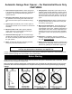
Automatic Garage Door Opener – For Residential Doors Only FEATURES 7. Safety System: Independent up and down force adjustments. When properly adjusted, the safety system will automatically reverse when obstructed in down direction and return to fully open position. The door will stop when obstructed in the up direction. See Adj. #2, pg 22. 1. Open and Close Cycle Control: Allows garage door to be started and stopped by push button, transmitter or wall station.
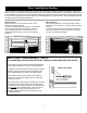
Door Tests Before Starting Before you begin, complete the following two tests to insure that the door is balanced and working properly. A door that binds, sticks or is out of balance could cause severe injury. Do not attempt to compensate for an improperly adjusted door by the installation of an opener. This will interfere with the proper operation of the opener mechanism and/or may damage the door.
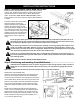
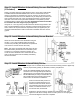
INSTALLATION INSTRUCTIONS Step 1: Attaching Motor Power Head Unit to Rail Before assembly, align sprocket/coupling cogs to match notches of driver gear. Rotate the Motor Spline to position Driver Gear so that the nearest notch in Driver Gear is directly behind Motor Spline, as illustrated. Note: Do not rotate more than ½ turn. Place opposite end of rail on temporary support approximately 6” in height.
Step 3: Attach Unit to Front Wall Bracket Raise the front end of the opener and attach it to the front wall bracket, using the ¼” x 4” hex head bolt and the supplied ¼” plastic insert nut. Take care not to over tighten nut; tighten only until end of bolt is flush with outside of nut. NOTE: If you have a torsion spring counterbalance system, it will be necessary to raise the motor Head Assembly of the opener and support it on a step-ladder to attach the front end of the opener to Wall Bracket.
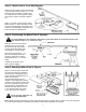
Step 6: Mounting Door Bracket Fiberglass, aluminum and steel doors must be reinforced to prevent damage to the door. Check with your garage door manufacturer for their recommendations. Reinforce light weight doors, as illustrated. For wood doors, mount door bracket, using two 1/4”-20 x 2” carriage bolts and 1/4” nuts supplied, on center line of door with middle hole in line with top rollers.
Step 9: Installing Deluxe Wireless Wall Station (if included) Install all wall controls out of the reach of children and in a location where the door can be seen before activating. Do not mount push buttons near or next to garage door. Locate a convenient place to mount wall station. To keep wall station out of the reach of children, measure at least five feet up from the floor and secure wall station base into wood wall framing using (2) Phillips head screws. Pilot drill mounting holes using a 3/32" bit.
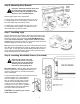
Step 11: Install Wireless Infrared Safety Sensors Wall Mounting Bracket (If Included) Select a mounting position 5 inches above the floor to center line of wall bracket. The EMITTER and TRANSPONDER units must be mounted inside the door opening to minimize any interference by the sun; however, the sensors must be mounted against the door track. The brackets may be temporarily mounted to the wall (or jamb) with a #8 X1/2” screw provided and should be in contact with the door track.
Step 14: Install Wired Infrared Safety Sensor Wall Mounting Brackets Use the following instructions if your opener is equipped with Wired Infrared Safety Sensors. If you just installed the Wireless Infrared Safety Sensors go to step 19. Select a mounting position 5 inches above the floor to center line of wall bracket. The sending and receiving units should be mounted inside the door opening to minimize any interference by the sun.
Step 16: Install Wiring for Wired Infrared Safety Sensor Identify which side of the garage door opening (if any) the sun is “likely” to shine on to. Since sunlight may affect infrared safety sensors, you should mount the sending unit on the side of the door opening exposed to the sun. Uncoil the wires from the infrared safety sensors and route the wire up the garage wall across the ceiling and down to the back of the power head, as illustrated. Tack the wires in place using staples.
Step 18: Mount Wired Infrared Safety Sensors Attach the sending and receiving units to the “U” brackets by inserting their tabs into their respective holes. Step 19: Connecting Electrical Power To reduce the risk of electrical shock, connect the power cord only to a properly grounded 3 prong, 120 volt outlet. Do not use an extension cord or change the plug in any way. At this point, plug in the opener to an electrical outlet.
Step 20: Wireless Wall Station Security Code Change and Programming Note: The following steps describe the process to change the Wireless Wall Station security code and to program the Wireless Wall Station to the opener. IMPORTANT: You MUST change the Wireless Wall Station security code prior to programming the device to the power head unit. WARNING: During programming the garage door may operate. Keep people and objects clear of the moving door to prevent door damage or possible personal injury.
Step 21: Alignment of the Wireless Infrared Safety Sensors Use the following instructions if your opener is equipped with Wireless Infrared Safety Sensors. If your opener is equipped with Wired Infrared Safety Sensors proceed to step 22. IMPORTANT: This infrared beam sensor sends an invisible beam of light from the emitter unit to the transponder unit across from the pathway of the door. The door opener will not operate until the safety sensor is programmed to the power head and it is properly aligned.
Step 22: Alignment of the Wired Infrared Safety Sensors Use the following instructions if your opener is equipped with Wired Infrared Safety Sensors. Otherwise proceed to step 23. IMPORTANT: This infrared beam sensor sends an invisible beam of light from the sending unit to the receiver unit across from the pathway of the door. The door opener will not operate until the safety sensor is connected to the power head and properly aligned.
Programming Transmitter to Power Head Unit Note: Do not press any button on the Transmitter until instructed 1. Press the PROGRAM Switch button located on the garage door power head unit once. The red PROGRAM STATUS light on the motor power head unit and overhead lamp will turn on and remain lit for one minute, indicating that it is ready to learn the Transmitter. 2. Press the button on the Transmitter you wish to use to operate the door.
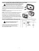
Step 24: Connecting Door Arm to Trolley Trolley must be at the factory preset fully close position. If not, activate opener to bring trolley to factory preset close limit, (see illustration). Door arm assembly consists of the upper arm (straight piece) and lower arm (curved piece). To assemble door arm, remove hairpin cotter from clevis pin at front of trolley and slide clevis pin out far enough to slide upper arm between left and right side of trolley body.
Step 27: Setting Door Close Travel Plus “Contact Obstruction Sensing” Test With wall control up/down button, activate door to full open position; reactivate to close position. The door should stop on the floor with the bottom door seal slightly compressed. If the door reverses off the floor, turn close travel knob 1/4 turn “less”. If door is not completely closed, turn travel knob 1/4 turn “more”. Repeat if necessary.
NOTE: Confirm that the door has stopped in the UP position as a result of the Upper Limit Switch and not because the Trolley has hit the open Stop Bolt, which is mounted in the Rail near the power head. The correct condition can be verified by observing that the openers Convenience Light does not flash after the fully open door comes to a stop. The faulty condition may also be confirmed visually by checking to see if the Trolley is resting against the stop bolt.
Step 31: Installing Wireless Keyless Entry (If Included) Install all wall controls out of the reach of children and in a location where the door can be seen before activating. CAUTION: The keypad should be mounted a minimum of 5 feet from the floor to keep it out of the reach of small children. Locate a convenient place to mount the Wireless Keyless Entry. Choose a convenient location that does not interfere with the normal opening and closing of the door.
OPENING FORCE ADJUSTMENT To determine that the opening force is not excessive, grasp the door handle or bottom edge during upward travel. If the opener does not stop or is hard to hold, decrease the open force setting. The opener should STOP without using excessive force. To change the opening force follow the procedure listed below. 1. Operate the door to the fully closed position. 2. Press the PROGRAM SWITCH button three times. The STATUS LED and the overhead lamp will flash on and off.
IMPORTANT SAFETY INSTRUCTIONS WARNING: To reduce the risk of severe injury or death: Before you proceed, please thoroughly read the safety rules on page 2 and the following operating instructions. Operate only when opener is properly adjusted and the door is visible and unobstructed. READ AND FOLLOW ALL INSTRUCTIONS. If possible, use the emergency release only when the door is closed. Use caution when using this release with the door open.
Operation of Your Opener HOW TO ACTIVATE THE OPENER Never let children operate or play with door controls. Keep remote control away from children. Use any of the following devices: 1. The Remote Control Transmitter; momentary push of the button and the door will start to move. 2. The Wall Station Up/Down button; push momentarily the button until the door starts to move. Constant push of the button, until door is closed is required if light flashes (indicating a Safety Sensor obstruction). 3.
HOW TO OPERATE THE WIRELESS WALL STATION (If Included) Never let children operate or play with door controls. Keep remote control away from children. The Wireless Wall Station Provides the Following Features: 1. Momentarily pressing the UP/DOWN button activates the door. An open door will close and a closed door will open. 2. Momentarily pressing the LIGHT button will toggle the overhead light on and off. The light will remain on until it is turned off by another LIGHT button press or the door is activated.
HOW TO OPERATE THE DOOR MANUALLY – Emergency Release Disconnect The door should be fully closed if possible, weak or broken springs could allow an open door to fall rapidly. Property damage or serious personal injury could result. Do not use the manual release knob to pull the door open or closed. Do not stand near or in the path of door when using the emergency release disconnect.
MAINTENANCE OF YOUR OPENER SYSTEM Test door opener monthly. The garage door MUST reverse on contact with a 1 inch high solid test object on the floor. If adjusting either the force or the limit of travel, retest the door opener. Failure to adjust the opener properly may cause severe injury of death. KEEP GARAGE DOORS PROPERLY BALANCED. See owner’s manual. An improperly balanced door could cause severe injury or death.
TROUBLE SHOOTING SECTION SYMPTOM PROBABLE CAUSE CORRECTIVE ACTION Opener won’t work from wall button or radio control. No power to opener. Check cord to outlet, wall switch and circuit breaker. Short circuit in wires to opener or wall button. Isolate by disconnecting the wires at the opener from the wall station. Motor Protector trips open due to excessive use. Radio control system non-operational. Allow motor to cool for 20 minutes and try again. Weak or dead battery in transmitterreplace.
Parts Breakdown Rail Assembly – All Models #. Part # Description # Per Unit #. Part # Description # Per Unit 1a. 1b. 2. 3. 4. 282903 282904 309957 309960 309959 Rail Angle, R.H. (7’) Rail Angle, L.H. (7’) Trolley Assembly Chain Latch Assembly Door Arm (Upper) 1 1 1 1 1 14. 15. 16. 17. 18. 220958 240956 308968 308969 305894 Front Rail Bracket Door Bracket 5/16x1/2” Clevis Pin 3/4” Diameter Retaining Ring Sprocket Coupling W/ Bushing 1 1 1 1 1 5. 309958 Door Arm (Lower) 1 19.
Parts Breakdown Power Head Assembly And Accessories – All Models #. Part # Description Per Unit #. Part # Description # Per Unit 1. 2. Frame Motor – 1/2 H.P. 1 1 18. 18a. 157166 157159 2 2 Motor – 1/3 H.P. 1 19. 157165 Wired Sensor Mounting Bracket Wireless Sensor Wall Mounting Bracket Wired Sensor Sliding Bracket 3. 157167 292123 or 291385 291386 or 291387 306132 1 19a 157162 Wireless Sensor Mounting Bracket 2 4. 5. 6. 7. 8.
QUANTUM ACCESSORIES Three Button mini/visor Transmitter Part# 302083 Controls up to 6 doors or wireless accessories. Includes visor clip. Wired Deluxe Wall Station Part# 306135 Allows independent door up/down control and overhead light on/off control. Unit will fit over a standard electrical outlet box. Wireless Deluxe Wall Station Part# 302090 Completely wireless unit with independent door up/down control, light on/off control, custom pet opening, delay exit timer, and program button.
Questions? For quick answers and helpful advice, Call Toll Free 1-888-827-3667 LIMITED LIFETIME WARRANTY The Manufacturer warrants that the Quantum™ garage door opener will be free from defects in materials and workmanship for a period of five years (3214, 3314), ten years (3316), and fifteen years (3414). Electronic components are warranted for three years (3214, 3314) and five years (3316, 3414).