Models 9100 / 9605 TorqueMaster® Plus Residential Standard Lift Ta b l e Of C o n te n ts Pre-Installation 2 Important Safety Instructions 2 Removing an Existing Door and Preparing the Opening 2 Package Contents 3 Door Section Identification 4 Tools Required 4 Breakdown Of Parts 5 Door Installation Instructions 6 Counterbalance Installation Instructions 10 Maintenance 16 Cleaning Your Garage Door 16 Painting Your Garage Door 16 Maintaining The Finish On Your Garage Door 16 Ope
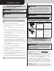
PRE-INSTALLATION CAUTION Important Safety Instructions IF ANY PART OF THE DOOR IS TO BE INSTALLED ONTO PRESERVATIVETREATED WOOD, PTFE-COATED OR STAINLESS STEEL FASTENERS MUST BE OBTAINED AND USED. REPLACEMENT FASTENERS MUST BE OF AT LEAST EQUAL STRENGTH AND SIZE AS ORIGINAL FASTENERS. IF THE ORIGINAL FASTENER WAS RED-HEAD, THE REPLACEMENT FASTENER MUST BE REDHEAD ALSO. CONTACT WAYNE DALTON FOR FASTENER STRENGTH VALUES IF NEEDED.
be firmly attached to the wall, above the header at the center of the opening. NOTE: Drill a 3/16” pilot hole in the mounting surface to avoid splitting the lumber. Do not attach the mounting surface with nails. (I2.) Spring tube assembly WEATHERSTRIPS (IF APPLICABLE): Depending on the size of your door, you may have to cut or trim the weatherstrips (if necessary) to properly fit into the header and jambs. NOTE: If nailing product at 40°F or below, pre-drilling is required. (A2.
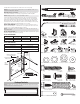
Door Section Identification Tools Required Graduated end and center hinges are always pre-attached at the top of each section (except top section) and the graduated end hinges are stamped for identification, #1, #2, #3, and #4 (#4 only on five section doors). The stamp identifies the stacking sequence of the section. The sequence is always determined by #1 being the bottom section to #3 or #4 being the highest intermediate section.
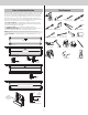
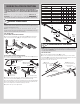
BREAKDOWN OF PARTS NOTE: The illustrations shown on this page are general representations of the door parts. Each specific door models may have unique variations. I5. H4. I4. H2. I2. I1. A1. F2. F1. I6. A2. E1. I5. A2. G1. J2. E2. I3. F1. J1. F2. B1. E3. H3. A1. H6. E4. C1. B1. A2. (Fully Adjustable Feature) A1. (Quick Install Feature) H1. D1. B1. (Quick Install Feature) H5. A. FLAG ANGLES (AS REQUIRED): H. TRACKS: A1. Quick Install (Q.I.) Flag Angles H1.
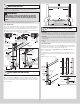
JAMB BRACKET SCHEDULE DOOR INSTALLATION INSTRUCTIONS BEFORE INSTALLING YOUR DOOR, BE CERTAIN THAT YOU HAVE READ AND FOLLOWED ALL OF THE INSTRUCTIONS COVERED IN THE PRE-INSTALLATION SECTION OF THIS MANUAL. FAILURE TO DO SO MAY RESULT IN AN IMPROPERLY INSTALLED DOOR. NOTE: Reference TDS 160 for general garage door terminology at www.dasma.com. IMPORTANT: IF THE DOOR WILL BE EXPOSED TO A SIGNIFICANT AMOUNT OF ROAD SALT, PAINT THE BARE GALVANIZED BOTTOM WEATHER STEEL RETAINER TO INHIBIT RUSTING.
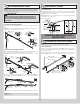
ATTACHING COUNTERBALANCE LIFT CABLES AND TRACK ROLLERS 3 Weatherstrips (If applicable) NOTE: Refer to door section identification, located in the pre-installation section of this manual or refer to Breakdown Of Parts. WARNING ENSURE TIGHT FIT OF CABLE LOOP OVER MILFORD PIN TO PREVENT COUNTERBALANCE LIFT CABLE FROM COMING OFF THE PIN, WHICH COULD ALLOW THE DOOR TO FALL AND RESULT IN SEVERE OR FATAL INJURY. Level NOTE: Verify bottom weather seal is aligned with bottom section.
6 (2) 1/4”-20 x 11/16” Self drilling screws (2) 1/4”-14 x 5/8” Self tapping screws ATTACHING STRUT(S) TO SECTION NOTE: Refer to Package Contents or Breakdown Of Parts, to determine which type of strut, if any, you received. 6” 30” To 36” STEP 6 INSTRUCTIONS 6” (2) 1/4”-20 x 11/16” Self drilling screws (2) 1/4”-14 x 5/8” Self tapping screws = IF YOUR DOOR CAME WITH A STRUT (U - SHAPED): 6a. Place the strut (U-shaped) (J1.) over the top rib of the top door section (E1.), as shown.
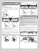
8 ATTACHING TOP FIXTURES NOTE: The top fixture slide will be tightened and adjusted later, in Step 12 Adjusting Top Fixtures. (H5.) Vertical track NOTE: Ensure the top fixture slide is able to slide along the top fixture base. If needed, loosen the 1/4” - 20 flange hex nuts. (H6.) Vertical track (E2.) Intermediate section STEP 8 INSTRUCTIONS (E3.) Second section 8a. To install the top fixtures, align the top holes in the top fixture base (F1.
11 12 ATTACHING HORIZONTAL TRACKS NOTE: Depending on your door, you may have Quick Install Flag Angles or Fully Adjustable Flag Angles. Refer to either the images below, Package Contents or Breakdown of Parts, to determine which Flag Angles you have. ADJUSTING TOP FIXTURES STEP 12 INSTRUCTIONS 12a. With horizontal tracks installed, you can now adjust the top fixtures. Vertically align the top section (E1.) of the door with the lower sections. Once aligned, position the top fixture slide (F2.
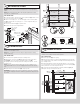
14 INSTALLING CABLE DRUM ASSEMBLIES STEP 14 INSTRUCTIONS Left hand cable drum Counterbalance lift cable 14b. Lift the spring tube assembly and rest it on top of the flag angles (A1.). NOTE: Temporarily support the center of the spring tube assembly until the center bracket (I1.) is installed in Step 16 Attaching Center Bracket to Wall. Label Winding shaft Spring tube assembly Round notch in flag angle Insert winding shaft into flag angle Splines 14e. Insert the idler bracket (I6.
15 16 ATTACHING END BRACKETS TO FLAG ANGLES IMPORTANT: Warning tags must be securely attached to end bracket(s). ATTACHING CENTER BRACKET TO WALL IMPORTANT: Spring tube must be level before securing center bracket bushing assembly to header. IMPORTANT: For single spring doors, ensure the left hand cable drum bearing is all the way to the left and up against the flag angle. If the cable drum is pulled away from the flag angle, then the idler bracket can rub against the cable drum causing noise.
18 19f. There are two methods for counting the spring turns as you wind. One method is to identify the black tooth on the ratchet wheel inside of the end bracket. When the wheel makes one revolution and the tooth returns to its starting point, one turn has been made. The other method is to make a mark on the winding shaft (or socket) and end bracket, and count your turns in this manner. ADJUSTING COUNTERBALANCE LIFT CABLE STEP 18 INSTRUCTIONS 19g.
20 ATTACHING REAR BACK HANGS Perforated angle bolted using (2) 5/16” x 1-5/8” hex head lag screws to ceiling member and parallel to door IMPORTANT: Hold the door down to prevent it from rising unexpectedly in the event the spring(s) were over-wound and cautiously remove locking pliers from vertical tracks. STEP 20 INSTRUCTIONS 20a. Raise the door until the top section and half of the next section are in the horizontal track radius.
22 BALANCING DOOR NOTE: Windows may cause the top section to be significantly heavier than the remaining sections. Wayne Dalton attempts to balance the door at the top and bottom. To prevent any sudden door acceleration between the top and bottom, we recommend motor operating all doors with windows. STEP 22 INSTRUCTIONS 22a. Remove any locking pliers. Lift the door and check its balance. Adjust spring(s) if door lifts by itself (hard to pull down) or if door is difficult to lift (drifts down).
MAINTENANCE available at no charge from Wayne Dalton, a division of Overhead Door Corporation, P.O. Box 67, Mt. Hope, OH., 44660, or at www.Wayne-Dalton.com. For additional information on garage door/operator maintenance go to www.dasma.com and reference TDS 151, 167 and 179. Cleaning Your Garage Door IMPORTANT: Do not use a pressure washer on your garage door! Monthly Inspections: While factory-applied finishes on garage doors are durable, it is desirable to clean them on a routine basis.
WARRANTY Limited Warranty Models 9100 and 9605 Wayne Dalton, a division of Overhead Door Corporation (“Seller”) warrants to the original purchaser of the Models 9100 and 9605 (“Product”), subject to all of the terms and conditions hereof, that the Product and all components thereof will be free from defects in materials and workmanship for the following period(s) of time, measured from the date of installation: LIMITED LIFETIME WARRANTY* on the Product sections against: • Peeling, cracking, or chalking of t
Thank you for your purchase. PLEASE DO NOT RETURN THIS PRODUCT TO THE STORE If you need assistance, please call 1-866-569-3799 (press Option 1) and follow the prompts to contact a customer service representative. They will be happy to handle any questions that you may have. After installation is complete, leave this Installation Instructions And Owner’s Manual with the homeowner, or fasten it near garage door for easy reference.
Modelos 9100 / 9605 TorqueMaster® Plus Residencial Elevación estándar Í n d i c e Preinstalación 2 Instrucciones de seguridad importantes 2 Remoción de una puerta existente y Preparación de la abertura 2 Contenido del paquete 3 Identificación de las secciones de la puerta 4 Herramientas necesarias 5 Desglose De Piezas 6 Instrucciones de instalación de la puerta 7 Instrucciones De Instalación Del Contrapeso 11 Mantenimiento 17 Limpieza de su puerta de garaje 17 Pintura de su puerta de g
PREINSTALACIÓN PRECAUCIÓN Instrucciones de seguridad importantes SI CUALQUIER PARTE DE LA PUERTA SE VA A INSTALAR SOBRE MADERA TRATADA CON CONSERVANTES, SE DEBEN OBTENER Y UTILIZAR SUJETADORES RECUBIERTOS CON PTFE O DE ACERO INOXIDABLE. LOS SUJETADORES DE REPUESTO DEBEN SER AL MENOS DE LA MISMA RESISTENCIA Y EL MISMO TAMAÑO QUE LOS SUJETADORES ORIGINALES. SI EL SUJETADOR ORIGINAL TENÍA LA CABEZA ROJA, EL SUJETADOR DE REPUESTO TAMBIÉN DEBE TENER LA CABEZA ROJA.
y 164 en www.dasma.com. El perímetro interior de la abertura de su puerta de garaje se deberá enmarcar con material de jamba y cabecero de madera. Las jambas y el cabecero se deben sujetar firmemente a miembros de enmarcado firmes. Se recomienda utilizar madera de 2 x 6 pulgadas. The jambs must be plumb and the header level. Las jambas deben estar a plomo y el cabecero debe estar nivelado.
ya sea derecho o izquierdo. NOTA: Las bisagras de extremo graduadas núm. 4 se utilizan en la cuarta sección de las puertas de cinco secciones. (F1.) Bases de los elementos de fijación superiores (F2.) Deslizadores de los elementos de fijación superiores (J1.) Puntal (con forma de U) (si se incluye) La SECCIÓN SUPERIOR (E1.) se puede identificar por no tener bisagras de extremo graduadas o centrales preinstaladas. (G1.) Soporte del operador de la barra de tracción Etiqueta de advertencias (J2.
Herramientas necesarias Vástago de Taladro eléctrico vaso: 7/16 de pulgada Brocas taladradoras: 1/8, 3/16, 9/32, 7/16 y 1/2 pulgada Llave de trinquete Alicates / Cortadores de alambre Destornillador de cabeza Phillips Abrazaderas de mordaza Caballetes Cinta métrica Llaves de tuerca: 3/8, 7/16,1/2, Extensión de trinquete de 3 pulgadas 9/16 y 5/8 de pulgada Nivel Destornillador de punta plana Llaves de vaso: 7/16,1/2, 9/16 y 5/8 de pulgada Martillo Escalera de tijera Guantes de cuero Gafas de se
DESGLOSE DE PIEZAS NOTA: Las ilustraciones que se muestran en esta página son representaciones generales de las piezas de la puerta. Es posible que cada modelo específico de puerta tenga variaciones especiales. I5. I4. H4. I2. H2. I1. F2. F1. I6. A1. A2. E1. I5. A2. G1. J2. E2. I3. F1. F2. J1. B1. E3. H3. A1. H6. E4. C1. B1. A1. (Dispositivo de instalación rápida) H1. D1. B1. (Dispositivo de instalación rápida) H5. A. ANGULARES ACARTELADOS (SEGÚN SEAN NECESARIOS): H. RIELES: A1.
INSTRUCCIONES DE INSTALACIÓN DE LA PUERTA TABLA DE SOPORTES PARA JAMBAS ALTURA DE LA PUERTA LONGITUD DEL RIEL ANTES DE INSTALAR SU PUERTA, ASEGÚRESE DE QUE HA LEÍDO Y SEGUIDO TODAS LAS INSTRUCCIONES CUBIERTAS EN LA SECCIÓN DE PREINSTALACIÓN DE ESTE MANUAL. SI NO LO HACE ASÍ, ES POSIBLE QUE EL RESULTADO SEA UNA PUERTA INSTALADA INCORRECTAMENTE. NOTA: Consulte la Hoja de datos técnicos TDS 160 para obtener terminología general de puertas de garaje en www.dasma.com.
3 INSTALACIÓN DE LOS CABLES DE ELEVACIÓN DE CONTRAPESO Y LOS RODILLOS PARA RIEL Burletes (si procede) NOTA: Consulte la identificación de las secciones de la puerta, ubicada en la sección de preinstalación de este manual, o consulte “Desglose de piezas”.
(2) Tornillos autoperforantes de 1/4 de pulgada - 20 x 11/16 de pulgada (2) Tornillos autorroscantes de 1/4 de pulgada - 14 x 5/8 de pulgada INSTALACIÓN DEL PUNTAL O LOS PUNTALES EN LA SECCIÓN 6 pulgadas 30 a 36 pulgadas NOTA: Consulte “Contenido del paquete” o “Desglose de piezas” para determinar qué tipo de puntal recibió, si es que recibió alguno. PASO 6, INSTRUCCIONES 6a. Coloque el puntal (con forma de U) (J1.) sobre la costilla superior de la sección superior (E1.
8 INSTALACIÓN DE LOS ELEMENTOS DE FIJACIÓN SUPERIORES NOTA: El deslizador del elemento de fijación superior se apretará y ajustará más tarde, en el Paso 12, “Ajuste de los elementos de fijación superiores”. (H5.) Riel vertical NOTA: Asegúrese de que el deslizador del elemento de fijación superior pueda deslizarse a lo largo de la base del elemento de fijación superior. Si es necesario, afloje las tuercas hexagonales con brida de 1/4 de pulgada - 20. PASO 8, INSTRUCCIONES (H6.) Riel vertical (E2.
11 11d. Repita el proceso para el otro lado. Retire el clavo que estaba sujetando temporalmente la sección superior en la posición deseada. IMPORTANTE: Si no se saca el clavo antes de intentar subir la puerta, el resultado podría ser daños permanentes a la sección superior. INSTALACIÓN DE LOS RIELES HORIZONTALES NOTA: Dependiendo de su puerta, puede que usted tenga angulares acartelados de instalación rápida o angulares acartelados completamente ajustables.
14 PARA APLICACIONES DE RESORTE DOBLE: Repita el proceso para el lado izquierdo. Punta de la leva directamente hacia arriba 1/2 vuelta del Eje de Cojinete cable de elevación enrollamiento de contrapeso Surco INSTALACIÓN DE LOS CONJUNTOS DE TAMBOR PARA CABLE PASO 14, INSTRUCCIONES 14a. Agite suavemente el conjunto del tubo de resortes (I2.) para extender los ejes de enrollamiento hacia fuera aproximadamente 5 pulgadas a cada lado.
INSTALACIÓN DE LOS SOPORTES DE EXTREMO EN LOS ANGULARES ACARTELADOS 15 16 INSTALACIÓN DEL SOPORTE CENTRAL EN LA PARED IMPORTANTE: Las etiquetas de advertencias deben estar firmemente colocadas en el soporte (los soportes) de extremo. IMPORTANTE: El tubo de resortes debe estar nivelado antes de fijar el conjunto de buje del soporte central al cabecero.
18 como izquierdo respondan igual. AJUSTE DEL CABLE DE ELEVACIÓN DE CONTRAPESO ADVERTENCIA 18b. Afloje el tornillo de ajuste no más de 1/2 vuelta. Asegúrese de que el cable de elevación de contrapeso esté alineado y asentado en el primer y el segundo surco del tambor para cable. Jale el extremo del cable para eliminar toda la holgura del cable.
Cable de elevación de contrapeso ADVERTENCIA (I3.) Soporte de extremo izquierdo MANTENGA LOS RIELES HORIZONTALES PARALELOS Y A UNA DISTANCIA DE ENTRE 3/4 Y 7/8 DE PULGADA COMO MÁXIMO DEL BORDE DE LA PUERTA, YA QUE DE LO CONTRARIO LA PUERTA PODRÍA CAERSE Y CAUSAR LESIONES GRAVES O MORTALES.
ADVERTENCIA 3/4 a 7/8 de pulgada 3/4 a 7/8 de pulgada Bordes de la puerta Rieles horizontales 21 SE DEBERÁ TENER PRECAUCIÓN EXTREMA AL ENROLLAR LOS RESORTES, YA QUE SI NO SE SIGUEN LAS INSTRUCCIONES O NO SE UTILIZAN LAS HERRAMIENTAS ADECUADAS, EL RESULTADO PUEDE SER LESIONES GRAVES A LAS PERSONAS Y DAÑOS MATERIALES GRAVES. ANTES INTENTAR ENROLLAR EL RESORTE. ASEGÚRESE DE QUE HA LEÍDO Y ENTENDIDO LAS INSTRUCCIONES.
MANTENIMIENTO IMPORTANTE: LAS CUERDAS DE TIRO SE DEBEN RETIRAR Y LAS CERRADURAS SE DEBEN RETIRAR O DEJAR INOPERANTES EN LA POSICIÓN DESBLOQUEADA. Limpieza de su puerta de garaje IMPORTANTE: ¡No utilice una roldana de presión en su puerta de garaje! Cuando conecte un operador de puerta de garaje de barra de tracción (tipo trole) a esta puerta, se debe instalar firmemente un soporte de operador de la barra de tracción en la sección superior de la puerta, junto con cualquier puntal provisto con la puerta.
itado en sistemas de puertas. 3. Lubricación: La puerta se debería abrir y cerrar suavemente. Asegúrese de que los rodillos para riel de la puerta estén rotando libremente cuando abra y cierre la puerta. Si los rodillos para riel no rotan libremente, limpie los rieles de la puerta, eliminando la suciedad y todas las sustancias extrañas.
GARANTÍA Garantía limitada Modelos 9100 y 9605 Wayne Dalton, una división de Overhead Door Corporation (el “Vendedor”), garantiza al comprador original de los Modelos 9100 y 9605 (el “Producto”), sujeto a todos los términos y condiciones del presente documento, que el Producto y todos los componentes del mismo estarán libres de defectos de materiales y de fabricación durante el siguiente o los siguientes períodos de tiempo, medidos desde la fecha de instalación: GARANTÍA LIMITADA DE POR VIDA* EN LAS SECCION
Gracias por su compra. POR FAVOR, NO DEVUELVA ESTE PRODUCTO A LA TIENDA Si necesita asistencia, sírvase llamar al 1-866-569-3799 (presione la Opción 1) y siga las indicaciones para contactar a un representante de servicio al cliente. Nuestros representantes se complacerán en atender cualquier duda que usted tenga.