
Installation Guide


be firmly attached to the wall, above the header at the center of the opening.
NOTE: Drill a 3/16” pilot hole in the mounting surface to avoid splitting the lumber. Do not
attach the mounting surface with nails.
WEATHERSTRIPS (IF APPLICABLE): Depending on the size of your door, you may have to
cut or trim the weatherstrips (if necessary) to properly fit into the header and jambs.
NOTE: If nailing product at 40°F or below, pre-drilling is required.
For the header, align the weatherstrip with the inside edge of the header and temporarily
secure it to the header with equally spaced nails. Starting at either side of the jamb, fit the
weatherstrip up tight against the temporarily attached weatherstrip in the header and flush
with the inside edge of the jamb. Temporarily secure the weatherstrip with equally spaced
nails. Repeat for other side. This will keep the bottom section from falling out of the opening
during installation. Equally space nails approximately 12” to 18” apart.
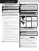
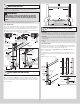
HEADROOM REQUIREMENT: Headroom is defined as the space needed above the top of
the door for tracks, springs, etc. to allow the door to open properly. If the door is to be motor
operated, 2-1/2” (64 mm) of additional headroom is required.
NOTE: 6” low headroom conversion kit is available for 12” radius only. Contact your local
Wayne Dalton dealer.
BACKROOM REQUIREMENT: Backroom is defined as the distance needed from the opening
back into the garage to allow the door to open fully.
BACKROOM REQUIREMENTS
DOOR HEIGHT TRACK MANUAL LIFT MOTOR OPERATED
6’5” to 7’0” 12”,15” Radius 98” (2489 mm) 125” (3175 mm)
7’1” to 8’0” 12”,15” Radius 110” (2794 mm) 137” (3480 mm)
HEADROOM REQUIREMENTS
TRACK TYPE SPACE NEEDED
15” Radius track 13-1/2” (343 mm)
12” Radius track 11” (279 mm)
6” LHR KIT 6” (152 mm)
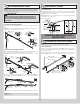
Weatherstrips
Level header
Finished
Door width
Jambs
Backroom
Plumb
jambs
Finished
Door
Height
Nail
Headroom
Header board 2”x 6”
lumber preferred
Suitable mounting surface
2”x 6” lumber minimum
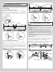
Weatherstrips
Jamb
Quick Install track
Min. Side
room
Clearance
is 3-1/2”
Min. Side
room
Clearance
is 3-1/2”
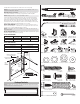
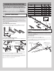
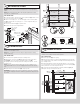
Package Contents
NOTE: Depending on the door model, some parts listed will not be supplied if not required.
Rear Back Hangs are not included with your door.
(E1. - E4.)
Door sections (as required)
(I2.)
Spring tube assembly
(A1.) Quick Install flag angles
RH/LH (as required)
(H5. - H6.) Vertical tracks RH/LH
(A2.) Fully Adjustable flag angles
RH/LH (as required)
(H3. - H4.)
Horizontal track angles
(H1. - H2.) Horizontal tracks RH/LH
(B1.) Quick install jamb
brackets (as required)
(I1.) Center bracket
bushing assembly
(I3.) Left hand en
d
bracket (as required)
Weatherstrips
(If included)
(I5.) Cable drum
assemblies RH/LH
(I6.) Idler bracket
(single spring only)
(C1.) Track rollers
(as required)
(F1.)
Top fixture bases
(F2.) Top fixture
slides
(G1.) Drawbar
operator bracket
3
00
5
4
7
RE
V3
1
2
/
1
6
/
20
2
0
©C
o
py
r
ight
2
0
2
0
W
a
yne
Da
l
to
n,
a
div
is
io
n
o
f
O
v
e
rhe
a
d
D
o
o
r
C
o
r
po
r
a
tio
n
Numb
e
r
o
f
Inst
a
ll
ed Spring Tur
n
s __
__
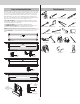
(I4.) Right
hand end bracket
(J1.) Strut
(U-shaped)
(if included)
(J2.) Strut
(A-symmetrical)
(if included)
(2) 3/8”- 16 Hex nuts
1/4”- 20 Flanged
hex nuts (as required)
(2) 5/16” Washers
(2) 5/16”-18 Hex nuts
5/16” x 1-5/8” Hex head lag screws
(as required)
(2) 5/16”-18 x 3/4”
Carriage bolts
1/4”-20 x 9/16”
Track bolts (as required)
(2) 3/8”-16 x 3/4”
Truss head bolts
(2) #12 x 1/2”
Phillips head screws
1/4”-14 x 5/8” Self tapping
screws (as required)
Cotter pin
5/16” x 1-1/4” Clevis pin
Stud Plate
(as required)
Rear Back Hangs
(If included)
3