
Installation Guide


DOOR INSTALLATION INSTRUCTIONS
BEFORE INSTALLING YOUR DOOR, BE CERTAIN THAT YOU HAVE READ AND FOL-
LOWED ALL OF THE INSTRUCTIONS COVERED IN THE PRE-INSTALLATION SECTION
OF THIS MANUAL. FAILURE TO DO SO MAY RESULT IN AN IMPROPERLY INSTALLED
DOOR.
NOTE: Reference TDS 160 for general garage door terminology at www.dasma.com.
IMPORTANT: IF THE DOOR WILL BE EXPOSED TO A SIGNIFICANT AMOUNT OF ROAD SALT,
PAINT THE BARE GALVANIZED BOTTOM WEATHER STEEL RETAINER TO INHIBIT RUSTING.
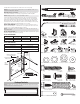
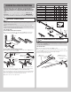
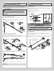
VERTICAL TRACK ASSEMBLY
1
NOTE: Depending on your door, you may have Quick Install Flag Angles or Fully Adjustable
Flag Angles. Refer to either the images below, Package Contents or Breakdown of Parts, to
determine which Flag Angles you have.
NOTE: The bottom jamb bracket is always the shortest bracket, while the center jamb
bracket is the next tallest. If three jamb brackets per side are included with your door, you
will have received a top jamb bracket, which is the tallest.
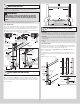
STEP 1 INSTRUCTIONS
FOR DOORS WITH QUICK INSTALL FLAG ANGLES:
1a. Place the lower Quick Install tab of the left hand flag angle (A1.) in the Quick Install
feature of the left hand vertical track (H3.). Give the flag angle 1/4 turn to lock in place.
1/4 Turn
(H3.) Left hand
vertical track
(A1.) Left hand quick
install flag angle
FOR DOORS WITH FULLY ADJUSTABLE FLAG ANGLE:
1a. Hand tighten the left hand flag angle (A2.) to the left hand vertical track (H3.) using (2)
1/4” - 20 x 9/16” track bolts and (1) stud plate.
Stud Plate
(2) 1/4”- 20
Flange hex nuts
12” Radius track15” Radius track
(2) 1/4”- 20 Flange hex nuts
Slot
Slot
12” Or 15”
Radius
(H1.) Horizontal
track
(A2.) Left hand fully
adjustable flag angle
(H5.) Left
hand vertical
track
(H5.) Left
hand vertical
track
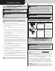
1b. Measure the length of the vertical tracks. Using the jamb bracket schedule, determine
the placement of the jamb brackets (B1.) for your door height and track length.
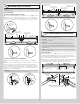
1c. To install the jamb brackets, align the Quick Install tab on the Quick Install jamb bracket
with the Quick Install feature in the vertical track and turn the bracket perpendicular to the
track so the mounting flange is toward the back (flat) leg of the track.
1d. Repeat the same process for right hand side.
6’5”
6’0”
6’8” 72” (1829 mm)
69” (1753 mm)
64” (1626 mm)
3
3
5
B
B
M
6
6
6
M
M
B
NA
NA
NA
B
B
M
7’0”
7’6”
7’3”
8’0” 4-SEC
7’9” 85” (2159 mm)
82” (2083 mm)
79” (2007mm)
88” (2235mm)
76” (1930 mm)
8’0” 5-SEC
B= BOTTOM HOLE, M= MIDDLE HOLE, T= TOP HOLE
88” (2235 mm)
3
3
3
3
3
3
B
B
B
M
B
B
5
5
5
6
7
7
B
B
B
T
T
T
6
6
6
7
NA
8
B
B
B
M
B
T
JAMB BRACKET SCHEDULE
2ND SET1ST SET 3RD SET
TRACK LENGTH
DOOR
HEIGHT
1/4
Turn
Left hand
jamb bracket
3rd
Set
1st
Set
2nd Set
Bottom
hole
Top
hole
Middle
hole
(H3.) Left
hand
vertical
track
(B1.) Left hand
jamb bracket
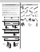
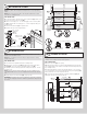
ATTACHING HORIZONTAL TRACK ANGLES
2
NOTE: For larger doors, a full length horizontal track angle may not already be spot welded
to the horizontal track (H1.)(H2.). If the horizontal track angle is not welded, the horizontal
track angle will be installed, as shown.
STEP 2 INSTRUCTIONS
2a. Position the left hand horizontal track angle (H3.), as shown.
2b. Place the Quick Install tabs of the horizontal track angle in the key slot of the left hand
horizontal track (H1.). Using a hammer, tap the horizontal track angle towards the curved end
of the track until the alignment hole in the track and angle are aligned.
2c. Repeat for other side. Set tracks aside.
(H3.) Left hand
horizontal track angle
Key slots
(H1.) Left hand
horizontal track
Quick
Install tabs
Quick Install tabs
in place
Left hand horizontal
track angle
Quick
Install tabs
Or
NOTE: Repeat the same
process for the right hand side.
6