
Installation Guide
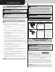

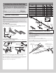
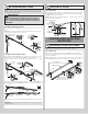

ATTACHING COUNTERBALANCE LIFT CABLES
AND TRACK ROLLERS
3
NOTE: Refer to door section identification, located in the pre-installation section of this
manual or refer to Breakdown Of Parts.
WARNING
ENSURE TIGHT FIT OF CABLE LOOP OVER MILFORD PIN TO PREVENT
COUNTERBALANCE LIFT CABLE FROM COMING OFF THE PIN, WHICH
COULD ALLOW THE DOOR TO FALL AND RESULT IN SEVERE OR FATAL
INJURY.
NOTE: Verify bottom weather seal is aligned with bottom section. If there is more than 1/2”
excess weather seal on either side, trim weather seal even with bottom section.
STEP 3 INSTRUCTIONS
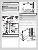
3a. Uncoil the counterbalance lift cables from the cable drum assemblies (I5.), making sure
you place the left hand cable loop on the left hand milford pin of the bottom corner bracket
and the right hand cable loop on the right hand milford pin of the bottom corner bracket.
3b. Insert a short stem track roller (C1.) into the bottom corner brackets and another into the
#1 graduated end hinges at the top of the bottom section (E4.).
Counterbalance
lift cable
Counterbalance
lift cable
Left hand cable
drum assembly
Cable loop
Cable loop
Right hand cable drum assembly
NOTE: Cable drum assemblies (I5.)
are marked right and left hand.
Left hand cable
drum assembly
(E4.) Bottom
section
Counterbalance
lift cable
(C1.) Short
stem track roller
Bottom
corner
bracket
warning
label
Bottom corner
bracket
warning label
#1 Single
graduated
end hinge
(Hinge tube)
Bottom
weather
seal
Left hand cable
drum assembly
#1 Single
graduated end
hinge (Hinge tube)
Milford
pin
Cable
loop
Short stem
track roller
Bottom
section
Counterbalance
lift cable
Bottom corner bracket
Short stem
track roller
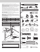
POSITIONING BOTTOM SECTION
4
STEP 4 INSTRUCTIONS
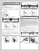
4a. Center the bottom section (E4.) in the door opening. Level the section using wooden
shims (if necessary) under the bottom section. When the bottom section is leveled, temporar-
ily hold it in place by driving a nail into the jamb and bending it over the edge of the bottom
section on both sides.
Weatherstrips (If applicable)
Level
(E4.) Bottom section
Wooden shims (If necessary)
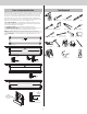
ATTACHING VERTICAL TRACKS TO JAMBS
5
IMPORTANT: If your door is to be installed prior to a finishing construction of the building’s
floor, the vertical tracks and the door bottom section assembly should be installed such that
when the floor is constructed, no door or track parts are trapped in the floor construction.
IMPORTANT: The tops of the vertical tracks must be level from side to side. If the bottom
section was shimmed to level it, the vertical track on the shimmed side must be raised the
height of the shim.
NOTE: Make sure the counterbalance lift cable is located between the track rollers and the
door jamb.
STEP 5 INSTRUCTIONS
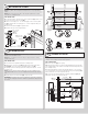
5a. Starting on the left hand side of the bottom section (E4.), remove the nail. Position the
left hand vertical track assembly over the track rollers (C1.) of the bottom section and install,
as shown. Drill 3/16” pilot holes into the door jamb for the lag screws.
5b. Loosely fasten jamb brackets (B1.) (B2.) and flag angle (A1.) (A2.) to the jamb using
5/16” x 1-5/8” lag screws.
5c. Tighten lag screws, securing the bottom jamb bracket to jamb, maintain 3/8” to 5/8”
spacing, between the bottom section and vertical track. Hang counterbalance lift cable over
flag angle.
5d. Repeat same process for other side.
Vertical
track
assembly
(B1.)(B2.)
Jamb
bracket
(A1.)(A2.)
Flag angle
Flag angle lag screw locations
5/16” x 1-5/8”
Lag screws
(E4.)
Bottom
section
(C1.) Track
rollers
3/8” to 5/8”
Spacing
Bottom section
15R QI12R QI
Floor
Track roller
Vertical track
12R Or 15R FAT
7