
Installation Guide


ATTACHING STRUT(S) TO SECTION
6
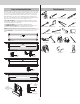
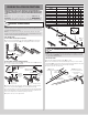
NOTE: Refer to Package Contents or Breakdown Of Parts, to determine which type of strut,
if any, you received.
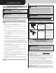
STEP 6 INSTRUCTIONS
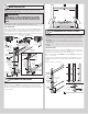
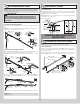
IF YOUR DOOR CAME WITH A STRUT (U - SHAPED):
6a. Place the strut (U-shaped) (J1.) over the top rib of the top door section (E1.), as shown.
6b. Fasten each end of the strut to the end cap with (2) 1/4” - 20 x 11/16” self drilling
screws. Fasten center of the strut as shown to the rib using (2) 1/4” - 14 x 5/8” self tapping
screws, one 6” to the left and one 6” to the right of the center line of the top door section.
=
=
(2) 1/4”-14 x 5/8”
Self tapping screws
(2) 1/4”-14 x 5/8”
Self tapping screws
Center line of top section
(2) 1/4”-20 x 11/16”
Self drilling screws
(2) 1/4”-20 x 11/16”
Self drilling screws
6”
6”
End cap
30” To 36”
(J1.) Strut
(U-shape)
(attached to
top rib)
(E1.) Top section
Top rib
Top section
Top section
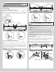
IF YOUR DOOR CAME WITH A STRUT (ASYMMETRICAL):
6a. Place the asymmetrical strut (J2.) over the top rib of the top door section (E1.), as
shown.
6b. Fasten each end of the asymmetrical strut to the end cap with (2) 1/4” - 20 x 11/16” self
drilling screws. Fasten center of the asymmetrical strut as shown to the rib using (2) 1/4” -
14 x 5/8” self tapping screws, one 6” to the left and one 6” to the right of the center line of
the top door section. Fasten both wall and the long leg of the asymmetrical strut, as shown
using (2) 1/4” - 14 x 5/8” self tapping screws every 30 - 36 inches. (Approximately 18 self
tapping screws per 18’ asymmetrical strut)
IMPORTANT: When securing the asymmetrical strut to the top section, it is recommended
not to install any fasteners into the short leg of the asymmetrical strut.
(J2.) Strut
(asymmetrical)
(attached to
top rib)
Strut
(asymmetrical)
(attached to top
rib)
Long leg
Short leg
Long leg
Short
leg
(E1.) Top section
Top section
Top ribTop rib
= =
(2) 1/4”-14 x 5/8”
Self tapping screws
(2) 1/4”-14 x 5/8”
Self tapping screws
Center line of top section
(2) 1/4”-20 x 11/16”
Self drilling screws
(2) 1/4”-20 x 11/16”
Self drilling screws
30” To 36”
6”
6”
End cap
Top section
Top section
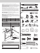
ATTACHING DRAWBAR OPERATOR BRACKET
7
NOTE: If you’re installing a drawbar operator, the drawbar operator bracket must be
mounted and secured prior to installing top section.
IMPORTANT: To avoid possible damage to your door, Wayne Dalton recommends reinforc-
ing the top section with a strut.
IMPORTANT: When connecting a drawbar operator type garage door opener to this door,
a Wayne Dalton operator/ drawbar operator bracket must be securely attached to the
top section of the door, along with any strut provided with the door. The installation of the
drawbar operator must be according to manufacturer’s instructions and force settings must
be adjusted properly.
NOTE: When attaching drawbar operator bracket to top section with strut, apply additional
pressure to thread into the strut.
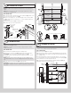
STEP 7 INSTRUCTIONS
7a. Prior to installing the top section (E1.), locate the center of the top section and seat
the drawbar operator bracket (G1.) on top of the top section. For retro fit applications, the
drawbar operator bracket must be aligned with an existing drawbar operator and positioned
on top section so it bridges the transition point of the section thickness.
7b. Install (2) #12 x 1/2” phillips head screws on the back side of drawbar operator bracket.
Clamp drawbar operator bracket to strut (if supplied) with vise clamps. Attach (6) 1/4” - 14 x
5/8” self-tapping screws to the drawbar operator bracket. Remove vise clamps.
=
(E1) Top section
Center line of
top section
Drawbar operator
bracket label
(2) #12 x 1/2”
Phillips head screws
1/4”- 14 x 5/8”
Self-tapping screws
(G1.) Drawbar
operator bracket
Backside of
drawbar operator
bracket
NOTE: Clamp drawbar operator bracket to
strut (if supplied) with vise clamps.
8