
Installation Guide

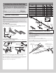

ATTACHING TOP FIXTURES
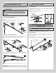
8
NOTE: The top fixture slide will be tightened and adjusted later, in Step 12 Adjusting Top
Fixtures.
NOTE: Ensure the top fixture slide is able to slide along the top fixture base. If needed,
loosen the 1/4” - 20 flange hex nuts.
STEP 8 INSTRUCTIONS
8a. To install the top fixtures, align the top holes in the top fixture base (F1.) with the second
set of holes in the end cap of the top section (E4.).
8b. Fasten to section using (4) 1/4” - 14 x 5/8” self tapping screws. Secure the top fixture
slide (F2.) to the fixture base loosely using (2) 1/4” - 20 x 5/8” carriage bolts and (2) 1/4” -
20 flange hex nuts.
8c. Insert short stem track roller (C1.) into top fixture slide.
8d. Repeat the same process for the right hand side.
(4) 1/4”- 14 x 5/8”
Self-tapping screws
(C1.) Insert short
stem track roller
(F1.) Top
fixture base
(F2.) Top
fixture slide
(2) 1/4”- 20 Flange hex nuts
End
cap
(2) 1/4”- 20 x 5/8”
Carriage bolts
2nd
Set
(E4.) Top
section
Top fixture slide
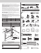
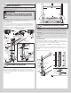
STACKING SECTIONS
9
NOTE: Refer to door section identification, located in the pre-installation section of this
manual or refer to Breakdown Of Parts.
NOTE: Make sure graduated end and center hinges are flipped down, when stacking
another section on top.
STEP 9 INSTRUCTIONS
9a. Place track rollers into graduated end hinges of remaining sections.
9b. With assistance, lift second section (E3) and guide the track rollers into the vertical
tracks (H5) (H6). Lower section until it is seated against bottom section (E4).
9c. Flip hinges up. Fasten center hinge(s) first; then end hinges last using 1/4” - 14 x 5/8”
self tapping screws.
NOTE: To prevent center hinge leaf from rotating, first secure the top middle hole of the
center hinge leaf with one 1/4” - 14 x 5/8” self-tapping screw then secure the other two
holes.
9d. Repeat same process for other sections (E2), except top section.
IMPORTANT: Push & hold the hinge leaf securely against the sections while securing with
1/4” - 14 x 5/8” self tapping screws. There should be no gap between the hinge leaves and
the sections.
(E2.) Intermediate
section
(E3.) Second
section
(E4.) Bottom
section
(H5.)
Vertical
track
(H6.)
Vertical
track
Center
hinge(s)
Left graduated end hinge
with short stem track roller
Right graduated end hinge
with short stem track roller
1/4”-14 x 5/8” Self tapping screw locations
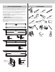
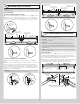
STACKING TOP SECTION
10
IMPORTANT: The dimension between the flag angles must be door width plus 3-3/8”
(86mm) to 3-1/2” (89 mm) for smooth, safe door operation.
STEP 10 INSTRUCTIONS
10a. Place the top section (E1.) in the opening.
10b. Install a nail to prevent the top section from falling backwards. Now, flip up the hinge
leaves, hold tight against section, and fasten center hinges first and end hinges last (refer to
Step 9 Stacking Sections).
10c. Vertical track alignment is critical. Position flag angle between 1-11/16” (43 mm) to
1-3/4” (44 mm) from the edge of the door; tighten the bottom lag screw. Flag angles (A1.)
must be parallel to the door sections. Repeat for other side.
10d. Complete the vertical track installation by securing the jamb bracket(s) (B1.) and
tightening the other lag screws. Repeat for other side.
(E1.) Top section
(E1.)
Top
section
Nail
Door width
+ 3-3/8” to 3-1/2”
1-11/16”
to 1-3/4”
(A1.)
Flag
angle
Vertical track
against track rollers
Flag angle
assembly
(A1.) Top of
flag angle
(B1.) Jamb bracket
9