
Operating instructions


4. A gate valve should be installed in the
system after the check valve. This gate
valve should be a full port valve which
will pass 2" solids or as required by
state and local codes. This gate valve
permits removal of the pump and/or
check valve for servicing.
5. A union should be installed between
the check valve and the pump so the
pump can be removed with least
disturbance of the piping.
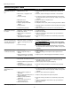
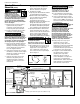
6. The RPP50 pump has a detachable
tether switch with a piggyback plug
(see Figure 3A). The length of the
tether (distance of cord from float to
clamp) should not be set shorter than
3-1/4 inches and should not be used in
a basin smaller than 14 inches in
diameter. If using a differential other
than the factory setting, be sure
when the pump shuts off at least 4”
of fluid is left in the basin so the
impeller remains submerged.
7. When any switch is used, rigid dis -
charge pipe is required. If the pump is
allowed to move, the tether switch
could be re strict ed by the basin wall,
pre vent ing the pump from operating.
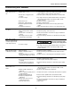
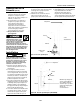
8. RPPCAP50 models are supplied with a
“Switch Genius” capacitive water
sensor. Orient the pump in the basin
so that the “Switch Genius” water
sensor is 180° away from the inlet.
3
Make certain the incoming water
stream does not hit the “Switch
Genius” surface (See Figure 3B).
Before
removing
pump from basin for service, always
disconnect electrical power to pump
and control switch. For any work on
pump or switch, ALWAYS unplug the
power cord. Do not just turn off circuit
break er or unscrew fuse.
Maintenance
Make
certain
that the pump is unplugged before
attempting to service or remove any
component. This pump is assembled in
the factory using special equipment;
therefore only authorized service dealers
or qualified electricians should attempt
to repair this unit. Improper repair can
cause an electrical shock hazard.
The pump
contains
oil that may be under pressure because
of heat. Let the pump cool for a minimum
of two hours before servicing this unit.
1. Disassembly of the motor prior to
expiration of war ran ty will void the
warranty. It might also cause internal
leakage and damage to the unit. If
repairs are required, return the pump
to the dealer from whom it was pur -
chased or call 1-800-237-0987.
2. After the basin cover is removed
and necessary dis charge piping
disconnected, lift pump from basin.
Check valve 45
o
Vent
Inlet
Gasket
1/2”
Min.
Clearance
Basin
Figure 3A - Prefabricated Basins (RPP50)
3. Pump should be checked on a
regular basis for proper op er a tion. If
anything has changed since unit was
new, the unit should be removed
and replaced. Only qualified
electricians or service peo ple should
at tempt to repair this unit. Improper
repair and/or assembly can cause an
electrical shock hazard.
4. Place the pump in a suitable area
where it can be cleaned
thoroughly. Remove all scale and
deposits on pump.
5. Submerge the complete pump in a
disinfectant so lu tion (10% chlorine
bleach solution) for at least one
hour before handling the pump.
6. For the RPP50, clean all dirt and
deposits from the pump float. Make
sure float moves freely after cleaning.
For the RPPCAP50 clean “Switch
Genius” water sensor surface.
7. Clean all dirt and deposits away
from pump inlet and volute.
This pump
contains
dielectric motor oil for lubrication and
motor heat transfer. This oil can be
harmful to the environment. Check
state environmental laws before
disposing of this oil. This oil can be
harmful to aquatic life so consideration
should be exercised in the application
of this pump.
www.waynepumps.com
Installation (Continued)
Check valve 45
o
Vent
Inlet
Gasket
Basin
Figure 3B - Prefabricated Basins (RPPCAP50)
Orient the pump so
that the “Switch-
Genius” is 180°
away from the
inlet. Make sure
the incoming water
stream does not hit
the “Switch-
Genius” surface.
Models RPP50 and RPPCAP50