Shallow Well Jet Pump System + Pre-Charged Tank Please read and save these instructions. Read carefully before attempting to assemble, install, operate or maintain the product described. Protect yourself and others by observing all safety information. Failure to comply with instructions could result in personal injury and/or property damage! Retain instructions for future reference. Operating Instructions and Parts Manual SWS50-8.
Operating Instructions and Parts Manual DESCRIPTION Shallow well jet pumps are single stage residential water pumps designed for pumping potable water in applications where the water is located less than 25 feet vertically from the pump. A pressure switch is a standard feature. The shallow well pump must be mounted to either a pre-charged, conventional type or free standing pressure tank. Intended for indoor use only.
Operating Instructions and Parts Manual GENERAL SAFETY INFORMATION (CONT'D) Disconnect power and release all pressure from the system before attempting to install, service, relocate or perform any maintenance. Lock the power disconnect in the open (OFF) position. Tag out the power disconnect to prevent unexpected application of power. Débrancher de la source d’alimentation puis dissiper toute la pression du système avant d’essayer d’installer, de réparer, de déplacer ou de procéder à l’entretien.
Operating Instructions and Parts Manual Step 1: NOTE: Remove pump from stabilizing mount, used for shipping and packing. MOTOR END HEX NUT With motor end of pump facing the “outlet / inlet” end of the tank, mount pump to tank with the provided carriage bolts, nuts and washers as shown (right). For easy installation, install bolts through bottom. HEX NUT WASHER The bolts can be entered in any slot to secure the pump providing they are positioned diagonally from one another.
Operating Instructions and Parts Manual SWS50-8.5FX Step 5: Screw pipe tee onto pipe nipple. Hand tighten. All connections will be fully tightened in steps 7 & 8. Step 6: Remove protective cover from tank’s outlet/ inlet, then screw hose-barb elbow onto tank. HOSE-BARB ELBOW Hand tighten. All connections will be fully tightened in steps 7 & 8. Step 7: With a pipe wrench, tighten pipe tee 1 to 1-1/2 turns, aligning hose-barb with pump as shown.
Operating Instructions and Parts Manual Step 9: NOTE: Lubricate the hose-barb and the inside of the hose with clean water or a small amount of liquid dish soap as needed. A Slip the hose clamps over the ends of the hose. B Attach the hose (with clamps) to the hose-barb using a twisting motion on the hose while pushing it over the hose-barb. A B B Step 10: Tighten the hose clamps on the hose over the hose-barb fittings.
Operating Instructions and Parts Manual SWS50-8.5FX PRE-INSTALLATION WATER STORAGE Flexible pipe is prohibited on suction pipe (inlet pipe). Tanks are required for these pumps to operate as designed. TANKS - CONVENTIONAL STORAGE The function of the tank is to store a quantity of water under pressure. When full, the tank contains approximately 2/3 water and 1/3 compressed air. Then compressed air forces the water out of the tank when a faucet is opened.
Operating Instructions and Parts Manual The foot valve MUST be at least 18” from the bottom of the well or sand or sediment WILL be drawn into the system. MISE EN GARDE Le clapet de pied DOIT au moins être à 45,7 cm (18 po) du fond du puits, sinon du sable ou des sédiments POURRAIENT être aspirés dans le système 4. After proper depth is reached, install a well seal or pitless adapter to support pipe and prevent surface water and other contaminants from entering well. 5.
Operating Instructions and Parts Manual ELECTRICAL Risk of electrical shock. This pump is designed for indoor installation unless housed and protected from the elements. Risque de choc électrique! Cette pompe est conçue pour une utilisation à l'intérieur, sauf si elle est à l'abri et protégée contre les intempéries. SWS50-8.5FX Disconnect power and release all pressure from the system before attempting to install, service, relocate or perform any maintenance.
Operating Instructions and Parts Manual MAINTENANCE OUTLET Disconnect power and release all pressure from the system before attempting to install, service, relocate or perform any maintenance. Lock the power disconnect in the open (OFF) position. Tag out the power disconnect to prevent unexpected application of power. Débrancher de la source d’alimentation puis dissiper toute la pression du système avant d’essayer d’installer, de réparer, de déplacer ou de procéder à l’entretien.
Operating Instructions and Parts Manual 8. Remove the seal plate. 9. Pry the rotating shaft seal member (including stainless collar and rubber seal) from the impeller (Figure 9). 10. Push or pry the ceramic seat, and rubber seat ring free from the seal plate (Figure 9). 11. Remove loose particles from impeller hub and seal plate. SWS50-8.5FX IMPELLER SEAL PLATE ROTATING SHAFT SEAL MEMBER RUBBER SEAT RING INSTALLING NEW SHAFT SEAL Before handling shaft seal parts wipe hands clean.
Operating Instructions and Parts Manual Replacement Part Kit Installation 1. Disconnect all power from the pump 2. Open faucet nearest the tank and allow all of the water to drain from the tank and pump. 3. Remove 4 cap screws, do not disconnect pressure switch. 4. Remove pump housing from pump assembly, move it out of the way. 5. Using a ¾” socket remove venturi from pump housing 6. Using a 11/16" socket and extension remove nozzle from pump housing 7.
Operating Instructions and Parts Manual SWS50-8.5FX TROUBLESHOOTING CHART Symptoms Possible Cause(s) Suggested Remedies Pump will not start or run 1. Power off 1. Turn power on or call power company 2. Blown fuse or tripped breaker 2. Replace fuse or reset circuit breaker 3. Faulty pressure switch 3. Replace 30/50 pressure switch 4. Motor overload tripped 4. Let cool. Overload will automatically reset 5. Low supply voltage 5. Contact an electrician 1.
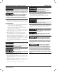
Figure 12 - Well Types (A) SPRING: A spring that emerges from the ground. Occurs when water in permeable materials is trapped between impermeable material as rock or clay. SHALE (B) LAKE, STREAM or POND: Surface water, unless treated, is usually not safe for human consumption. It may be used for purposes such as washing or irrigation. (B) LAKE, STREAM, POND (A) SPRING (D) DRIVEN WELL: Pipe with a pointed screen is driven into the ground below the water table.
Operating Instructions and Parts Manual SWS50-8.5FX LIMITED WARRANTY For three years for SWS50-8.5FX Series models from the date of purchase, from an authorized dealer, Wayne Water Systems will repair or replace, at its option for the original purchaser, any part or parts of its Well Pumps or Water Pumps (“Product”) found upon examination by Wayne Water Systems to be defective in materials or workmanship. Please call Wayne Water Systems (800-237-0987) for warranty instructions.