
User's Manual


FCC ID: 2ACHTQ7S
10
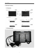
3-3 GPIO_DEMO Interface
3-3-1 GpioJni Demo as shown below
3-3-2 The file system path of the gpio port corresponding device node folder.
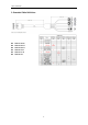
GPIO Interface
Yellow
Red
White
Green
Black
IN/OUT
Input 1
Input 2
Output 1
Output 2
GND
GpioJniDemo
Gpio14
Gpio58
Gpio68
Gpio88
The path of the Gpio68 node in the folder is: /sys/class/gpio/gpio979/
The path of the Gpio58 node in the folder is: /sys/class/gpio/gpio969/
The path of the Gpio88 node in the folder is: /sys/class/gpio/gpio999/
The path of the Gpio14 node in the folder is: /sys/class/gpio/gpio925/
3-3-3. How to read or set the value of gpio port.
READ: Read the value directly within the device node folder, function is asfollows, please refer to the usage
within demo for more details.
public String gpioReadStateOne(String state)
Read the data: ON ----the gpio port input is low level
OFF----the gpio port input is high level
SETTING: Write the value directly within the device node folder, function is asfollows, please refer to the
usage within demo for more details.
public boolean gpioSetStateOne(String name, int state)
Set a value: ON----set the gpio port output as high level
OFF---set the gpio port output as low level
GPIO:Input Voltage range: 0-3.3V ; output Voltage range:0-3.3V
3-4 ACC
3-4-1 ACC Connection Instruction:
connecting the tablet with vehicle power supply through extended cable or docking station, and
connecting ACC wire on extended cable of the tablet with ACC of vehicle.
ACC wire: