
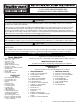
User guide
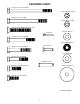


Cotter Pin
Clevis Pin
NOTE: Turn the Flow Control
counter clockwise to release
pressure. Adjust Flow Con-
trol Screw Per Instruction De-
cal On Handle Tube after
final assembly and installa-
tion.
(3) 3/8" Flat
Washer
5/16-18 x 4-1/2"
Hex Hd. Bolt
(A)
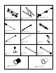
STEP 11
I
nsert Aluminum Bushing (A) into Rear
Cross-Member (B). Attach back of Cylinder (C)
to crossmember by installing 5/16-18 x 4-1/2"
Fastener. NOTE: After installing Bolt, apply
Loctite 290 to threads, then install the nut.
(C)
STEP 12
Attach front of Cylinder as shown. Bend over
Cotter Pin after inserting it through Clevis Pin.
5/16-18 Nylon
Lock Nut
(B)
CYLINDER INSTALLATION
11
10