
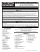
Manual
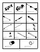
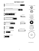


Cotter Pin
Clevis Pin
NOTE: Turn the Flow Control
counter clockwise to release
pressure. Adjust Flow Con-
trol Screw Per Instruction De-
cal On Handle Tube after
final assembly and installa-
tion.
(3) 3/8" Flat
Washer
5/16-18 x 4-1/2"
Hex Hd. Bolt
(A)
S
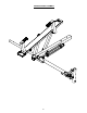
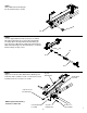
TEP 9
Insert Aluminum Bushing (A) into Rear
Cross-Member (B). Attach back of Cylinder (C)
to crossmember by installing 5/16-18 x 4-1/2"
Fastener. NOTE: After installing Bolt, apply
L
octite 290 to threads, then install the nut.
(C)
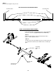
STEP 10
Attach front of Cylinder as shown. Bend over
Cotter Pin after inserting it through Clevis Pin.
5
/16-18 Nylon
Lock Nut
(B)
C
YLINDER INSTALLATION
10
9