
Installation Guide


We’re happy to help. Call 1-855-224-9761
.
17
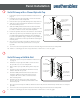
High Wind Installation
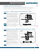
T&G Privacy with Picket Accent - 110 MPH sustained winds with
gusts to 130 MPH
Step 1
Reinforce each post to at least 22" above
ground with either an aluminum insert
(prior to installing the fence) OR fill each
post with concrete (after installing the
fence) as shown in figure 1. If using
concrete, be sure to tape off the rails to
prevent it from flowing into the rails.
Step 2
Install one #10 x 1" self-tapping stainless
steel screw into the top and bottom of
each 6" wide picket securing it to the
bottom and mid-rails. Screws should be
placed no more than 1" from the top or
bottom of the rail. Be careful not to over
tighten the screws.
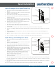
Step 3
Secure every other 1.5" wide accent picket
by installing a screw through the top rail
and through the mid-rail.
Step 4
Install a screw inside the post on each side
of the top rail as seen in figure 2.
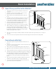
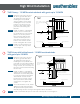
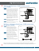
T&G Privacy with Aluminum Spindle Accent- 110 MPH sustained winds
with gusts up to 130 MPH.
Step 1
Reinforce each post to at least
22" above ground with either an
aluminum insert (prior to installing
the fence) OR fill each post with
concrete (after installing the fence) as
shown in figure 1. If using concrete,
be sure to tape off the rails to prevent
it from flowing into the rails.
Step 2
Install one #10 x 1" self-tapping
stainless steel screw into the top
and bottom of each 6" wide picket
to secure the picket to the top and
the bottom rails. Screws should be
placed no more than 1" from the top
or bottom of the rail. Be careful not to
over tighten the screws.
Step 3
Install a screw inside the post on each
side of the top rail as seen in figure 2.
Please note, the purchaser has the sole responsibility to determine whether these products comply with
applicable codes and is appropriate for the intended use. The purchaser and installer should review the intended
use of the products with a licensed professional engineer to determine code compliance and intended use.
32" min.
22" min.
Ground level
Top view of rail in posts
Place screw herePlace screw here
Place screws no more
than 1" from the edge
of the rail
Concrete or aluminum insert
(at least 54" tall)
12" X 36" post hole filled
with concrete
32" min.
22" min.
Ground level
Top view of rail in posts
Place screw here
Place screw here
Place screws no more
than 1" from the edge
of the rail
Concrete or aluminum insert
(at least 54" tall)
12" X 36" post hole filled with
concrete
Figure 1
Figure 2
Figure 1
Figure 2