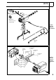
Air Heater Unit Feel the drive Air Top 2000 ST B Additional Heater Air Top 2000 ST D Additional Heater e1 *2001/56*0022 Installation Instructions VW T5 Gasoline and Diesel from Model Year 2004 For left-hand drive vehicles only WARNING! Hazard warning: Incorrect installation or repair of Webasto heating systems may cause a fire or result in the emission of carbon monoxide, which can be fatal. Serious or fatal injuries can be caused as a result.
VW T5 Table of Contents Validity Heater Units Foreword General Instructions Special tools Explanatory Notes on the Document General Installation Diagram Preliminary Work Heater Unit Installation Location Preparing Installation Location Preparing Heater Unit Installing Heater Unit Combustion Air Fuel Connection Metering Pump Fuel Removal on Vehicles without Additional or Auxiliary Heater 2 3 3 3 3 4 5 6 6 7 8 9 10 11 12 Fuel Removal on Vehicles with Additional or Auxiliary Heater Exhaust System Optional Ex
VW T5 Heater Units/Installation Kit Quantity 1 1 1 1 1 Description Order No.: Standard Delivery Scope Air Top 2000 ST Gasoline Standard Delivery Scope Air Top 2000 ST Diesel Comfort Delivery Scope Air Top 2000 ST Gasoline Comfort Delivery Scope Air Top 2000 ST Diesel Installation kit for VW T5 Gasoline and Diesel 9008324C 9008321C 9008325C 9008322C 9014156A The installation kit contains the bracket with fastening parts.
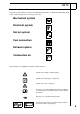
VW T5 Explanatory Notes on Document To provide you with a quick overview of the individual working steps, you will find an identification mark on the outside top right corner of the page in question. Mechanical system Electrical system Hot air system Fuel connection Exhaust system Combustion air Special features are highlighted using the following symbols: Specific risk of injury or fatal accidents. Specific risk of damage to components. Specific risk of fire or explosion.
VW T5 General Installation Diagram Digital timer: comfort accessory Not with TRS! Installation diagram for AT 2000 ST Fuel filter: option Jumper Terminal 15 0.75 mm² sw Terminal 30 1.0 mm² Terminal 58 rt 0.75 mm² gr 0.75 mm² br Terminal 31 1.0 mm² br 0.5 mm² sw 0.5 mm² bl Connection diagram for comfort digital timer 0.5 mm² rt 0.
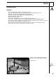
VW T5 Preliminary Work WARNING! - Disconnect the battery "earth" or "ground" connection. Copy the factory number from the original type label to the duplicate type label. Remove years that do not apply from the duplicate label. Attach the duplicate label (type label) in the appropriate place. Open fuel tank cap, ventilate tank. Close the tank cap again. Remove the underbody protection on the right and left (if present).
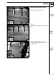
VW T5 1 Preparing installation location 1 1 Rivet nut (2x) in existing holes Installing rivet nuts 2 1 2 2 Bracket 1 M6x20 bolt, large diameter washer on rivet nuts 1 7 Loosely mount bracket 3 1 1 Copy hole pattern [2x] to door sill 2 Remove bracket, drill 9.1 mm dia.
VW T5 Preparing heater unit 1 With fresh-air mode, an underride protection as shown in Figure 33 must be installed if not present! 3 2 1 Heater unit 2 Mount base seal 3 Protective grill Preparing heater unit 5 1 2 3 Cut approx. 360 mm off 60 mm dia. flexible tube. 4 3 4 1 2 Heater unit Wiring harness 60 mm dia. flexible pipe, 360 mm long 50-70 mm dia. hose clamp Premounting heater unit 6 1 Route through wire of metering pump 4 downward. Fasten hot-air flexible tube on bracket with cable tie.
VW T5 1 2 Installing heater unit 1 2 Preassembled heater unit 1 M6x20 bolt, spring lockwasher, flanged nut [2x each] Installing heater unit 9 1 2 2 1 Preassembled heater unit 2 M6x20 bolt, spring lockwasher, flanged nut [2x each] Installing heater unit 10 9
VW T5 1 2 Combustion air 1 i Shape combustion-air intake pipe as shown in picture.
VW T5 Fuel Connection CAUTION! Open the vehicle's fuel tank cap, ventilate the tank and then re-close the tank lock. Catch any fuel running off with an appropriate container. Install fuel line and metering-pump wiring harness so that they are protected against stone impact. Unless specified otherwise, always fasten using cable ties. Mount the fuel line and wiring harness with rub protection on sharp edges.
VW T5 1 2 3 Metering pump 4 Cut Mecanyl fuel line to length at installation location of metering pump. 6 2 5 1 4 6 4 3 Ensure proper installation position of metering pump, see "Installation Instructions“.
VW T5 Fuel Removal on Vehicles without Additional or Auxiliary Heater 1 Remove fuel tank according to manufacturer's specifications. Remove fuel-tank sending unit according to manufacturer's specifications. Cut out template and lay on. 2 3 1 Fuel-tank sending unit 2 Template 3 Copy hole pattern, 6 mm dia. hole Removing fuel 18 Shape fuel standpipe according to template, cut to length and install, see "installation instructions".
VW T5 1 Fuel Removal on Vehicles with Additional or Auxiliary Heater 1 Cut off fuel line to additional or auxiliary heater as shown. Mount fuel standpipe in cutting point as shown. 4 3 2 22 1 Fuel line to additional or auxiliary heater 2 Fuel standpipe, 10 mm dia. hose clamp [2x]. 4 Remaining end of Mecanyl fuel line from metering pump 3 Hose section, 10 mm dia.
VW T5 1 Exhaust system 2 Align exhaust pipe as shown. Drill 2 mm dia. condensed-water drain hole at lowest point in exhaust pipe. Ensure sufficient distance to neighboring components.
VW T5 Optional Hot Air System WARNING! The routing of the air ducting parts shown is an application example on the van with a partition wall. Should other versions and equipment variants be used, then the appropriate adjustments must be made. Before installation, the routing of the air ducting parts must be coordinated with the end customer! Install flexible tubes so that they are kink-free. Unless specified otherwise, always fasten using brackets and cable ties.
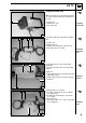
VW T5 Optional Hot Air System 1 Fold back cover under front passenger seat. Lay on dia. 55x60 adapter as shown. 2 2 Dia. 55x60 mm adapter 1 Copy hole pattern, 60 mm dia. hole Hole under front passenger seat 27 Mount adapter in hole from above and glue in with Sicaflex. 1 1 Dia. 55x60 mm adapter Gluing in adapter 28 1 Mount 60 mm dia. flexible tube on adapter. Route wiring harness of controls through protective rubber plug into passenger compartment. 2 4 1 3 2 3 4 60 mm dia.
VW T5 Cut 55 mm dia. flexible tube 1 to length as shown and mount on adapter 3. 1 3 2 1 55 mm dia. flexible tube 3 50-70 mm dia. hose clamp 2 Bracket with hose clamp, self-tapping screw [2x] Routing under front passenger seat 31 1 6 2 5 4 3 Cut 55 mm dia. flexible tube 3 and 5 to length as shown. Mount air distributor as shown. Air outlet must be aligned so that hot air is not directed at controls (e.g. handbrake lever)! 1 4 3 5 2 6 55 mm dia.
VW T5 Optional Recirculating Air No underride protection is required for the option recirculating air mode! 1 Underride protection Underride protection 33 1 1 Lay air outlet on entrance trim on front passenger side as shown; copy inside dia. and hole pattern for fastening [3x] to trim. Remove air outlet and drill 60 mm dia. hole in trim and entrance on front passenger side. 2 1 Entrance trim on front passenger side 2 Air outlet Installing air outlet 34 1 Hole for fastening air outlet [3x] in trim.
VW T5 1 2 Electrical Connections 3 4 Fuse holder retaining plate, M4x12 bolt, washer, M4 nut 1 Wiring harness of power supply for heater unit 2 Ground wire on negative battery terminal 3 Positive wire on positive battery terminal Installing fuse holder 4 37 1 Thermostat 1 i Installing heater control 38 Combination timer option 1 i 1 Combination timer Installing combination timer 39 External temperature sensor 1 Installation is not carried out in recirculating air mode! 1 External tempera
VW T5 Remote option (Telestart) 1 i Connect receiver for Telestart as shown in wiring diagram. 2 1 M5x16 bolt, flanged nut on existing hole 2 Telestart 3 Telestart bracket Installing receiver 41 3 Only applies for combination of standard heater control with Telestart! Connect switch as shown in wiring diagram.
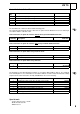
2 1 ws bl sw rt S9 rt br 2 11 10 12 13 X6 A1 rt 1 M1 M br ge E 3 br X2 1 2 3 rt rt 2 ge B1 8 X8 B4 2 br ϑ 1 Y1 bl sw/bl 1 1 2 X4 8 ϑ ge 9 X6 B2 7 sw R1 2 ϑ br 1 15 3 sw X8 br 2 X5 14 S6 1 5 br X1 F2 F1 2 B3 X10 bl 1 4 16 X6 17 9 3 4 S5 ϑ bl 2 A2 X3 5 6 2 X11 sw/rt 85 86 S4 ws/rt 31 H1 4 3 X9 T80 gn/ws S1 30 15 M 87 F3 M3 0 30 31 1 2 K 87a 7 3 30 15 1 2 2 3 4 2 1 1 2 2 1 X11 1 X9 X
X12 9 6 8 2 ws bl rt sw rt T80 br br 2 11 10 13 12 rt 1 A1 X6 M1 M br ge E 3 br X2 3 2 rt X1 1 F1 2 ge B1 8 X8 B4 2 br ϑ 1 Y1 bl sw/bl 1 1 2 X4 8 9 X6 B2 ϑ 7 ge R1 2 ϑ br 1 15 3 sw X8 br 2 X5 14 S6 1 5 sw S7 4 H3 11 F2 2 B3 X10 bl 1 4 3 16 X6 17 9 4 S5 ϑ bl 2 A2 X3 5 6 2 X11 sw/rt 85 86 S4 ws/rt 31 7 H4 10 6 br 12 P 1 1 gn/ws H5 30 15 58 M 87 F3 M3 0 30 31 1 2 K 87a 7 3 30 15 58 3 1
VW T5 1 With positive wire from terminal (15/75) to connection 10: Continuous operation with immediate heating as long as ignition is switched on Without positive wire on connection 10: Heating time is variably programmable (10 min. to 120 min.), default setting is 120 min.
VW T5 Pos. Name Remarks A1 A2 B1 B2 B3 B4 E F1 F2 F3 H1 H3 Heater unit Control unit Flame detector Temperature sensor Overheating sensor Temperature sensor Glow element 24 V 15 A/12 V 20 A fuse Fuse, 3 A 25 A fuse LED, green (in Pos. S1) LED, red (in Pos. P) Air Top 2000 ST H4 H5 H6 K M1 M3 P R1 S1 S2 S3 S4 S5 S6 S7 S8 S9 V1 V2 X1 X2 X3 X4 X5 X6 X7 X8 X9 X10 X11 X12 Y1 Y2 Heating symbol in display (in Pos. P) Lamps (in Pos. P) Lamp (at least 1.
VW T5 Shut-down on fault Faults in individual heater unit components and malfunctions during the entire operation are recognized in the control unit.
VW T5 Final Work WARNING! Reassemble the disassembled components in reverse order. Check all hoses, hose, spring and Caillau clamps, as well as all electrical connections for firm seating. Secure all loose cables using cable ties. Spray the heater unit components with anti-corrosion wax (Tectyl 100K, Order No. 111329). - Connect the battery - Set the digital timer. - Check the proper operation of the air heater, see the operating instructions/installation instructions.
VW T5 Operating Instructions for End Customer Please remove page and add to the vehicle operating instructions. Only for vehicles with standard heater control and Telestart! On vehicles with additional heater or auxiliary heater from factory, the fuel level may not be below 1/4 of a tank for proper operation of the Air Top 2000 ST air heater! Before parking the vehicle, make the following settings: 1. 2.
VW T5 Template for Fuel sender 100 mm Scale 1:1 Compare the size of the printed version with dimension lines. Permitted tolerance a maximum of 2%. Correct major differences in the printer settings or request an original printout.
VW T5 Template for Fuel Standpipe 100 mm Scale 1:1 Compare the size of the printed version with dimension lines. Permitted tolerance a maximum of 2%. Correct major differences in the printer settings or request an original printout.